Manufacturing system with intrinsically safe electric information storage

a manufacturing system and intrinsic safe technology, applied in the field of storage and distribution systems, can solve the problems of volatile chemicals used in manufacturing and production environments, and conventional systems do not allow electrical communication with storage containers, and achieve the effect of suppressing transient voltage surges

Active Publication Date: 2006-12-26
ADVANCED TECH MATERIALS INC
View PDF8 Cites 23 Cited by
  • Summary
  • Abstract
  • Description
  • Claims
  • Application Information

AI Technical Summary

Benefits of technology

[0009]As another example, the manufacturing system may be a system for handling hazardous liquids. The system for handling hazardous liquids includes a container capable of holding a liquid. An electric storage device is coupled with the container for electrically storing information relating to the liquid stored in the container. The system also has an antenna for storing information to and reading information from the electric storage device. The system includes a microprocessor-based controller, coupled with the antenna, for controlling processing of the liquid based on information read from the electric storage device by the antenna. Finally, an intrinsic safety barrier is connected between the antenna and the controller to limit electrical energy entering the hazard zone.
[0010]In a preferred embodiment, the intrinsic safety barrier includes a plurality of forward conduction diodes connected in parallel between the controller and ground, typically arranged in a multiple redundancy configuration. The intrinsic safety barrier preferably further includes a fuse connected in series with the plurality of forward conduction diodes to prevent overloading the plurality of forward conduction diodes and to limit the amount of power passed into the hazard zone. A plurality of blocking capacitors may be connected in series with the controller and the antenna to block a DC component of the signal coming from the controller. Further, at least one resistor may be connected in series with the controller and the antenna to suppress transient voltage surges at the antenna.

Problems solved by technology

At times, chemicals used in manufacturing and production environments are volatile, and must be stored in a controlled hazard area.
Conventional systems do not allow for electrical communication with the storage containers in the hazard area.

Method used


Image

  • Manufacturing system with intrinsically safe electric information storage
  • Manufacturing system with intrinsically safe electric information storage
  • Manufacturing system with intrinsically safe electric information storage

Examples


Embodiment Construction

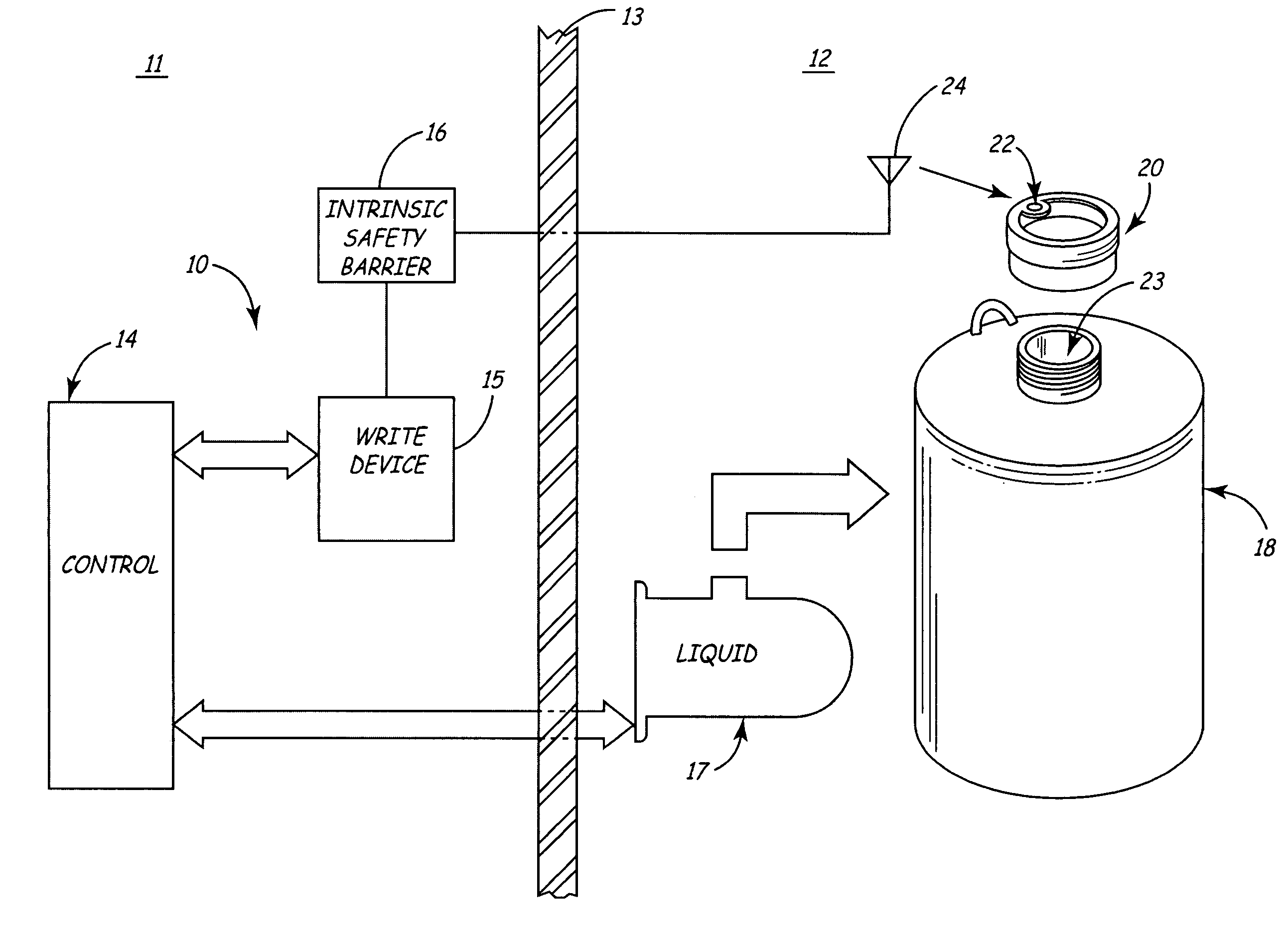
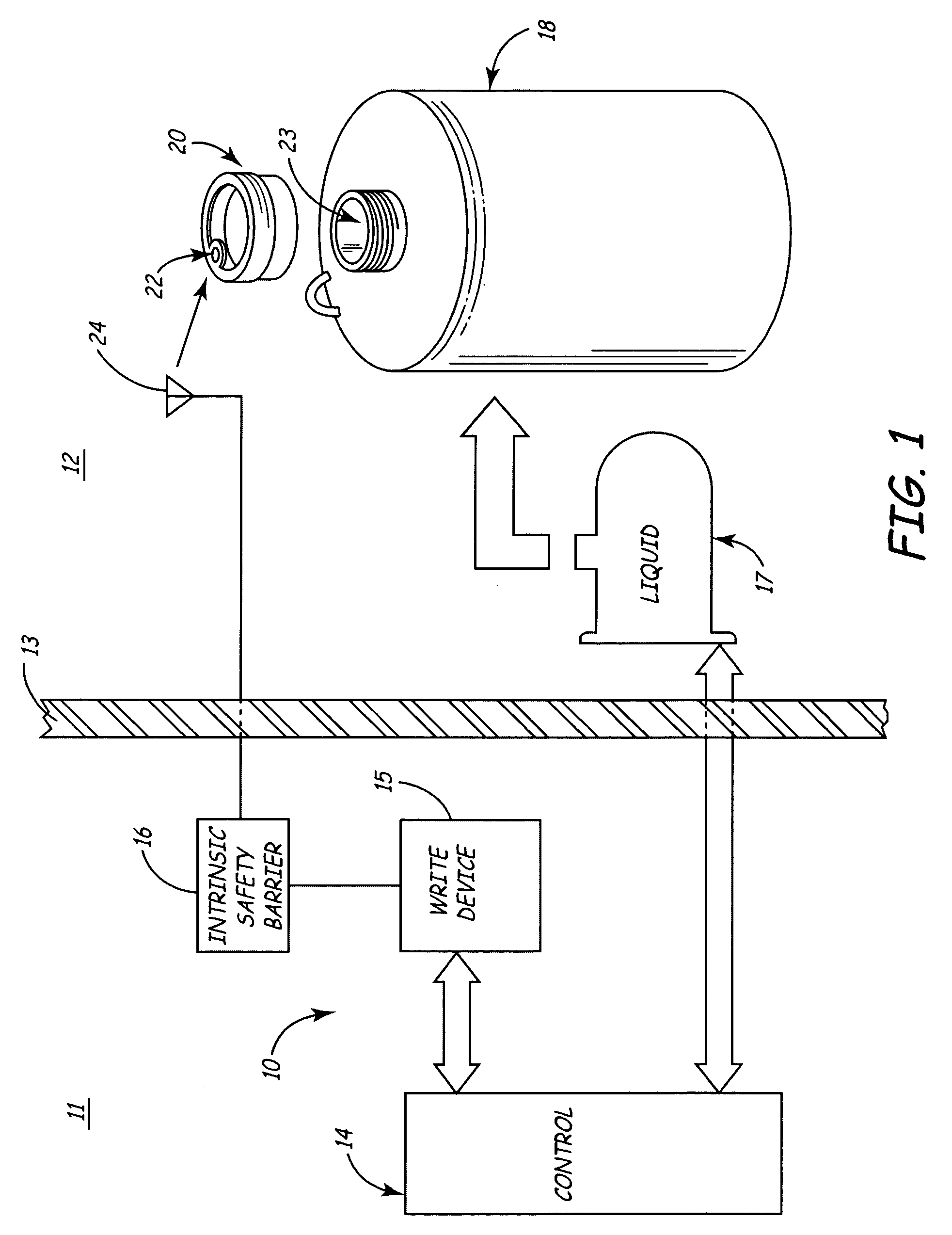
[0014]FIG. 1 shows filling system 10 for filling a container with a volatile or combustible liquid. Filling system 10 includes non-hazard zone 11 and hazard zone 12 separated by explosion protection wall 13. In non-hazard zone 11, filling system 10 includes microprocessor-based control unit 14, write device 15, and intrinsic safety barrier 16. In hazard zone 12, filling system 10 includes liquid reservoir 17, container 18 and cap 20. Control unit 14 is electrically connected to write device 15 and liquid reservoir 17. Control unit 14 is preferably a microprocessor-based computer system, and write device 15 is preferably a radio frequency (RF) card connected to the microprocessor-based computer system. Liquid reservoir 17 is in fluid communication with container 18. Cap 20 includes radio frequency identification (RFID) tag 22. RFID tag 22 includes an electrically-erasable programmable read-only memory (EEPROM) and a passive RF transponder. Write device 15 is capable of writing to RFI...


PUM


Abstract

The present invention is a manufacturing system including a hazard zone and a non-hazard zone. The system includes a storage device, located in the hazard zone, for electrically storing information. The system further includes a communication device, also located in the hazard zone, for storing information to and reading information from the storage device. In the non-hazard zone, a controller is in electrical communication with the communication device. The controller controls the system based on information read from the storage device by the communication device. To limit electrical energy passing to the communication device, an intrinsic safety barrier located in the non-hazard zone is connected between the communication device and the controller device.

Description

BACKGROUND OF THE INVENTION[0001]This invention relates to a storage and dispensing system for the storage and dispensing of liquids. In particular, the invention relates to a radio frequency identification (RFID) antenna including an intrinsic safety barrier for use in a hazardous liquid dispensing environment.[0002]Certain manufacturing processes require the use of liquid chemicals such as acids, solvents, bases, photoresists, dopants, inorganic, organic and biological solutions, pharmaceuticals, and radioactive chemicals. Storage and dispensing systems allow alternative containers to be used to deliver liquid chemicals to a manufacturing process at a specified time.[0003]These containers include an electric storage device attached to the cap of each container which contains information about the chemical stored inside the container. For example, a radio frequency identification (RFID) tag may be attached to the container, the RFID tag including a place for electric information st...

Claims


Application Information

Patent Timeline
Patent Type & Authority Patents(United States)
IPC IPC(8): G06F7/00G05B19/042G06F17/00G06K
CPCG05B19/0425G05B2219/25293G05B2219/24028G06K17/00H01Q21/00G06K19/07
Inventor O'DOUGHERTY, KEVIN T.BAILLIE, BRYAN
Owner ADVANCED TECH MATERIALS INC
Why Eureka
Try Eureka