Releasable tubing connector

a tubing connector and releasable technology, applied in the field of surgical instruments, can solve the problems of depression and other medical problems, the inability to manipulate these things, and the limitation of the mobility of the catheter user, and achieve the effect of convenient operation

Inactive Publication Date: 2006-12-26
MITCHELL MARTIN S
View PDF11 Cites 88 Cited by
  • Summary
  • Abstract
  • Description
  • Claims
  • Application Information

AI Technical Summary

Benefits of technology

[0004]In light of the problems associated with the known products for connecting tubular surgical instruments, it is a principal object of the invention to provide a releasable tubing connector that can be easily operated by virtually anyone. The connector can be used to connect and disconnect two lengths of tubing without resort to additional tools and long periods of training.
[0005]It is another object of the present invention to provide a tubing connector of the type described that prevents fluids from siphoning from two lengths of tubing when such are disconnected from one another. Similarly, fluids, such as air, are prevented by the tubing connector from entering into two lengths of tubing when such are disconnected from one another.
[0006]It is an object of the invention to provide improved elements and arrangements thereof in a tubing connector for the purposes described which is lightweight in construction, inexpensive to manufacture, and fully dependable in use.

Problems solved by technology

Despite their widespread use and great utility, catheters limit the mobility of a user, tethering him to a fluid collector.
Over long periods of time, such a loss of mobility can lead to depression and other medical problems.
Unfortunately, many infirm or elderly individuals cannot manipulate these things and, hence, find them to be useless.

Method used


Image

  • Releasable tubing connector
  • Releasable tubing connector
  • Releasable tubing connector

Examples


Embodiment Construction

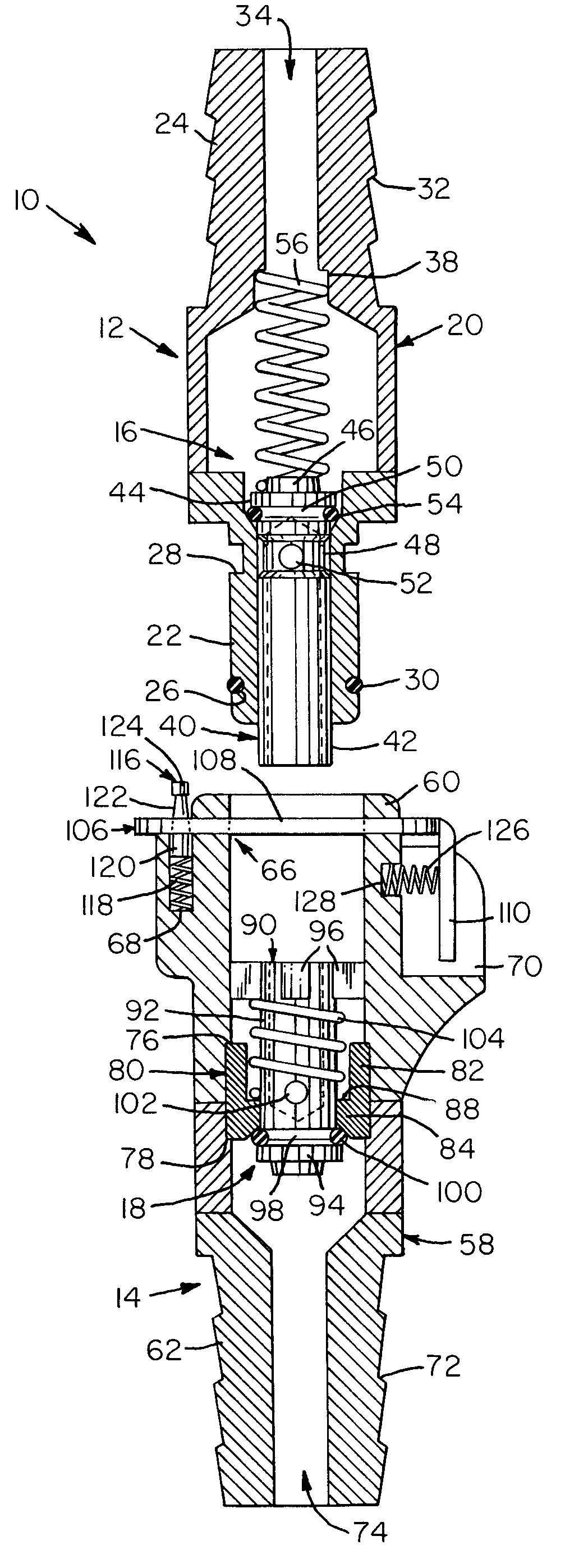
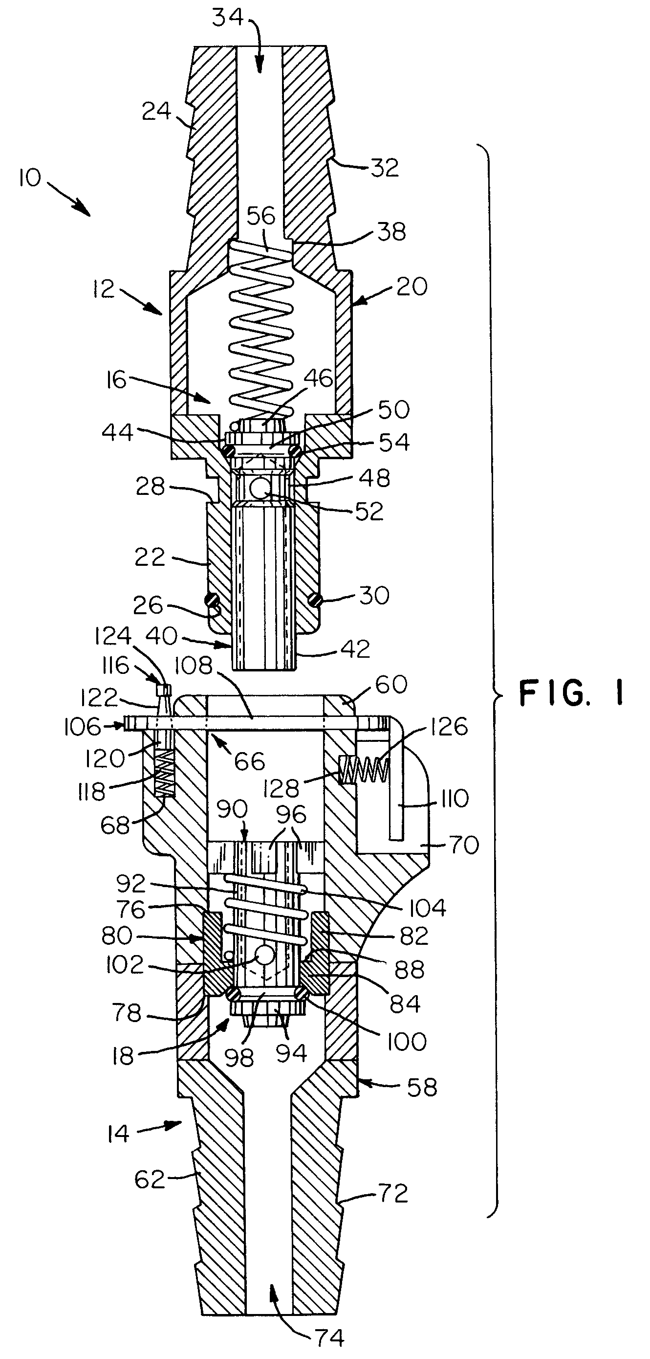
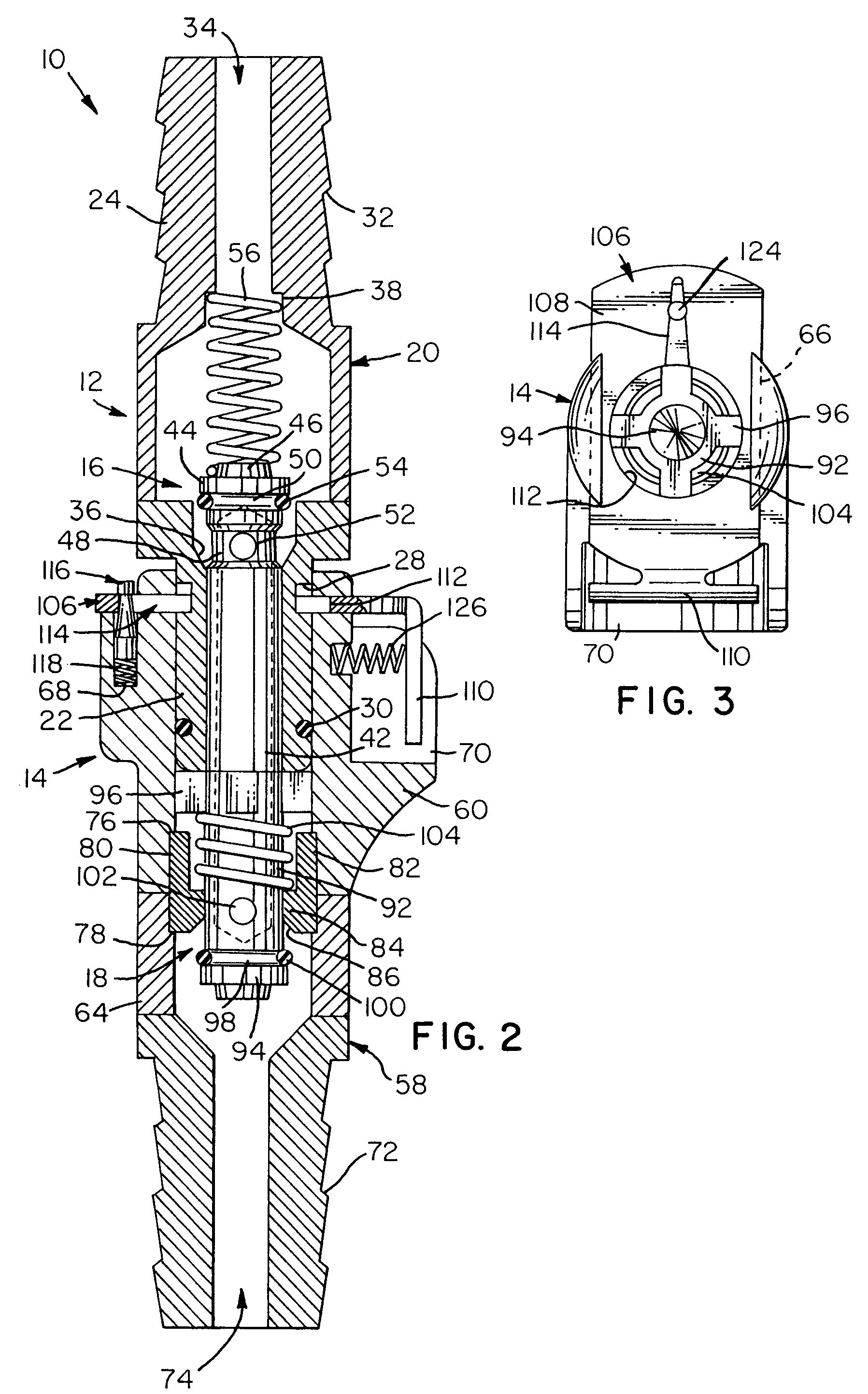
[0014]Referring now to the FIGS., a tubing connector in accordance with the present invention is shown at 10. Tubing connector 10 has a male part 12 that can be selectively fastened to a female part 14. Parts 12 and 14 are provided with internal valve assemblies 16 and 18 that cooperate with one another to permit fluid to flow through tubing connector 10.

[0015]Part 12 comprises a tubular body 20 having a plug 22 and a tubing insert 24 joined together at their inner ends. Preferably, plug 22 is cylindrical in form and has peripheral grooves 26 and 28 at its inner and outer ends. Peripheral groove 26 carries an O-ring 30. Tubing insert 24 is also cylindrical and has a plurality of side-by-side grooves 32 with sloping floors that serve to secure part 12 to a length of tubing (not shown).

[0016]Plug 22 and tubing insert 24 are hollow and define a passageway 34 extending from one end of tubular body 20 to the other. Passageway 34 can be seen to be enlarged somewhat at the inner end of plu...


PUM


Abstract

A releasable tubing connector including a male part that can be selectively fastened to a female part. The male and female parts are provided with internal valve assemblies that cooperate with one another to permit fluid to flow through the tubing connector. When the male and female parts are fastened together, fluid can flow through the releasable tubing connector. On the other hand, when the male and female parts are unfastened, fluid can flow through neither.

Description

FIELD OF THE INVENTION[0001]The present invention relates generally to surgical apparatus and, more particularly, to aseptic connectors or couplings.BACKGROUND OF THE INVENTION[0002]Individuals undergoing medical treatments in hospital settings frequently find themselves connected to catheters which are tubular surgical instruments for withdrawing fluids from a cavity in the body. In normal use, one end of a catheter is introduced into the bladder through the urethra for withdrawing urine and the other end is connected to a bag or bottle for collecting the withdrawn urine. Despite their widespread use and great utility, catheters limit the mobility of a user, tethering him to a fluid collector. Over long periods of time, such a loss of mobility can lead to depression and other medical problems.[0003]Products have been proposed that permit catheters and other tubular surgical instruments to be parted. Many of these products utilize small components or portions that are rotated relati...

Claims


Application Information

Patent Timeline
Patent Type & Authority Patents(United States)
IPC IPC(8): A61M25/16A61M25/18A61M39/00A61M39/10
CPCA61M39/10A61M39/1011A61M39/26A61M2039/1027Y10S604/905
Inventor MITCHELL, MARTIN S.
Owner MITCHELL MARTIN S
Why Eureka
Try Eureka