Magnetic connector apparatus

a technology of magnets and connectors, applied in the direction of magnets, magnets, snap fasteners, etc., can solve the problems of not providing magnetic connector bodies nor connector magnet structures capable of or arranged for the magnetic connection of multiple magnetic connector bodies, and achieves the effect of simple connector magnet structure and economical manufactur

Active Publication Date: 2006-12-26
GYMWORLD
View PDF10 Cites 145 Cited by
  • Summary
  • Abstract
  • Description
  • Claims
  • Application Information

AI Technical Summary

Benefits of technology

[0012]A still further object and advantage of this invention is the provision of a magnetic connector apparatus of the class described which utilizes an extremely simplified connector magnet structure for economical manufacture and reliability and durability in use.

Problems solved by technology

While these various connector magnet structures may, as taught, be well suited for association with the panel face surfaces forming the side walls of multi-sided block-type magnetic connector bodies to be joined magnetically together in mutually aligned, sidewall-to-sidewall, face-to-face condition, they do not provide magnetic connector bodies nor connector magnet structures capable of or arranged for magnetic connection of multiple magnetic connector bodies in edge-to-edge condition along mutually confronting, linearly peripheral edges of the connector bodies.

Method used


Image

  • Magnetic connector apparatus
  • Magnetic connector apparatus
  • Magnetic connector apparatus

Examples


Embodiment Construction

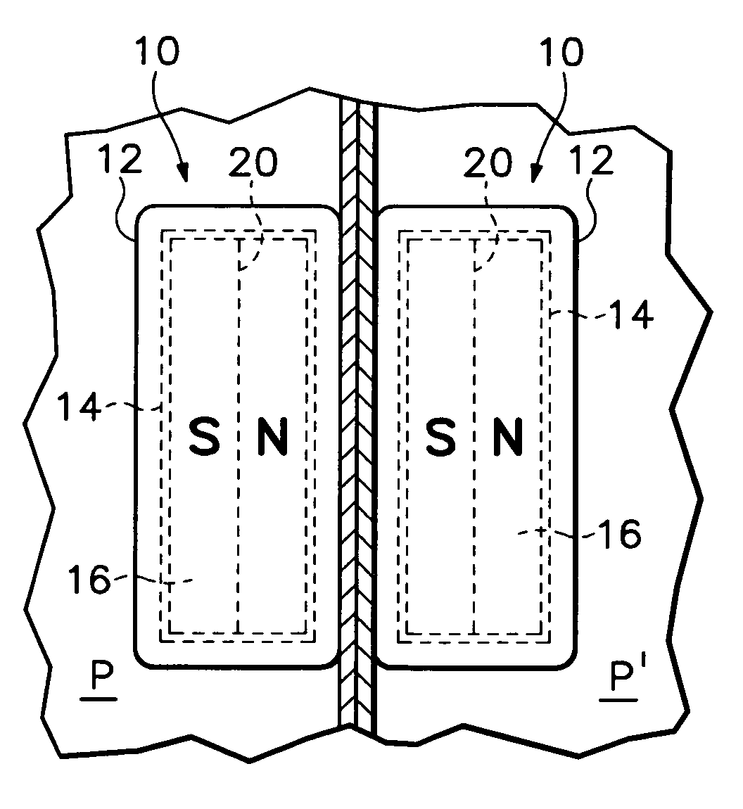
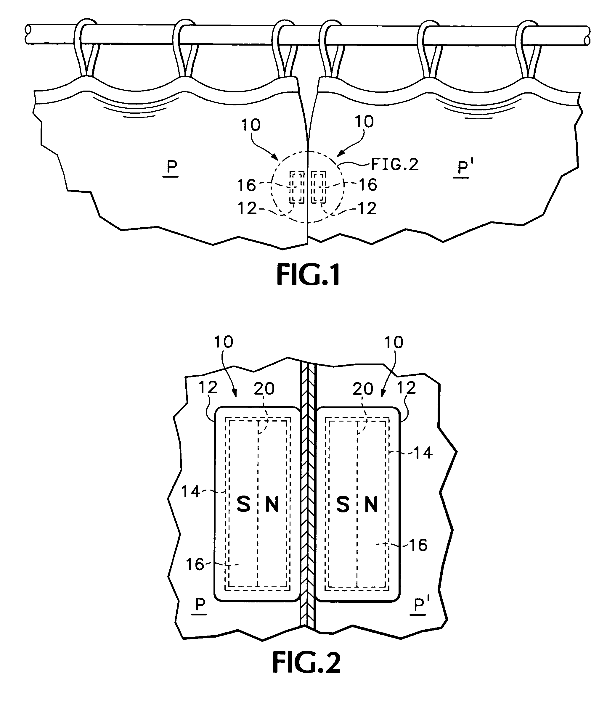
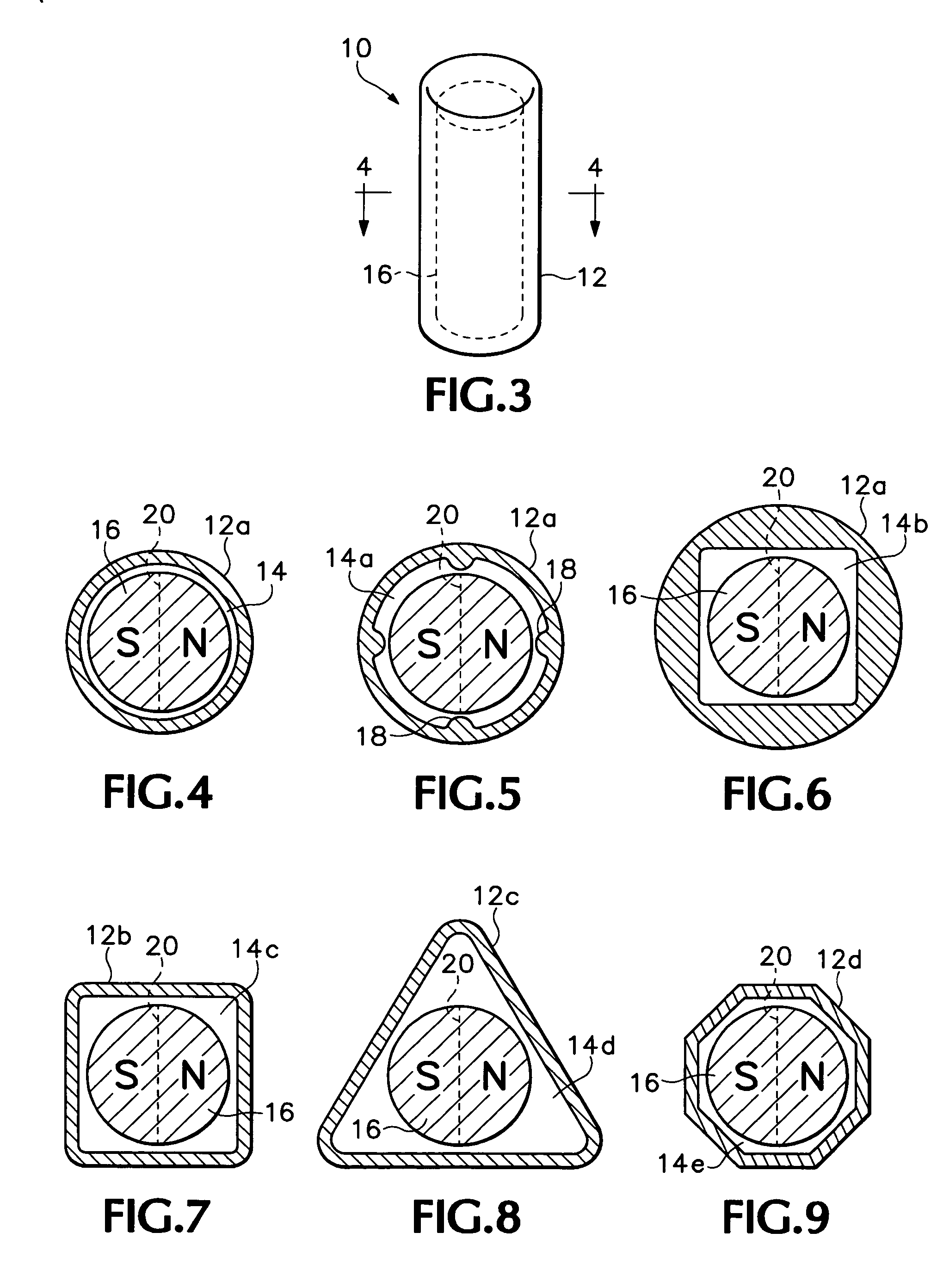
[0029]A magnetic connector apparatus embodying features of the present invention is illustrated herein in various different illustrative embodiments, each embodiment utilizing the basic, essential structural elements unique to this invention as will now be described in detail. FIGS. 1–3 illustrate a first embodiment of the magnetic connector apparatus of this invention, the connector apparatus comprising at least two magnetic connector bodies 10 (a pair being shown herein), provided for mutual magnetic attraction along adjacent on confronting, linear peripheral border edges thereof to each other. FIG. 3 is a perspective view showing a single connector body of the first embodiment in detail, while FIGS. 1 and 2 are schematic illustrations of a pair of connector body members 10 forming a connector apparatus shown in a working environment wherein the magnetic connector bodies are secured on a pair of drapery panels P, P′ adjacent their respective confronting free ends, whereby to posit...


PUM

PropertyMeasurementUnit
lengthaaaaaaaaaa
magneticaaaaaaaaaa
magnet structureaaaaaaaaaa

Abstract

A magnetic connector apparatus provides a plurality of magnetic connector bodies in various different forms for magnetic connection of two or more bodies together along mutually-confronting, longitudinally-elongated, linear peripheral border edges, each linear peripheral border edge having at least one particularly-configured longitudinally elongated, cylindrical magnet supported adjacent thereto for rotation of the magnet adjacent said peripheral edge of each connector body for orientation of the magnetic polarity of magnets of confronting connector bodies for mutual magnetic attraction along, mutually confronting, linear peripheral border edges of magnetic connector bodies.

Description

[0001]This application claims benefit under 35 U.S.C. 119(e) of the prior filing of U.S. Provisional Ser. No. 60 / 639,005 filed 23 Dec. 2004.BACKGROUND OF THE INVENTION[0002]This invention relates to magnetic connector arrangements, and more particularly to magnetic connector arrangements utilizing magnets retained rotatably in magnet containing pockets of multiple connector bodies provided for mutual magnetic attraction one to another, each respective magnet rotating in its pocket as needed for proper orientation and alignment of the respective opposite magnetic poles of the respective magnet as the connector bodies are moved toward each other and into magnetically-attracted connection one to another.[0003]Such magnetic connector arrangements have been provided heretofore, as represented by the various structural arrangements and teachings of U.S. Pat. No. 5,347,253 to Ogikubo; U.S. Pat. No. 5,746,638 to Shiraishi; and my own earlier U.S. Pat. No. 6,749,480 issued 15 Jun. 2004. In t...

Claims


Application Information

Patent Timeline
Patent Type & Authority Patents(United States)
IPC IPC(8): H01F7/02A63H33/04H01F7/20
CPCH01F7/0242A47H2201/01Y10T24/32
Inventor HUNTS, LARRY DEAN
Owner GYMWORLD
Why Eureka
Try Eureka