Electronic paper, electronic paperfile and electronic pen

a technology of electronic paper and paper file, applied in the field of electronic paper, electronic paper file and electronic pen, can solve the problems of insufficient display, inability to remove and carry out only a specific electronic paper, and inability to confirm the display conten

Inactive Publication Date: 2006-12-26
PANASONIC CORP
View PDF26 Cites 77 Cited by
  • Summary
  • Abstract
  • Description
  • Claims
  • Application Information

AI Technical Summary

Benefits of technology

[0026]Additionally, the display 11 of the electronic paper 10 is provided with a display layer A comprising the nonvolatile display medium possible to perform the pattern display, as shown in FIG. 3. According such configuration, the display data is displayed on the nonvolatile display medium, and in result the electronic paper detached from the main unit 20 can retain the display content.
[0027]Moreover, where the display 11 of the electronic paper 10 is configured to be provided with a luminescence layer B for illuminating the display layer A, it is possible to confirm the display content of the electronic paper 10 in the dark.

Problems solved by technology

However, regarding the legibility and user-facility, such display mediums are not superior to the “paper” that has been used as an information medium from a long time ago.
In case of the volatile display medium, the display goes dark when the electronic paper is cut off from the power.
However, after the display content is deleted temporarily in order to rewrite, a user has to execute the rewriting.
However, regarding the above-mentioned conventional electronic paper file it is impossible to remove and carry out only a specific electronic paper since the electronic paper and the main unit itself (the front board) controlling the electronic paper are integrated in one unit.
However, in case of using the volatile display medium as above, when the electronic paper is removed from the main unit, it becomes impossible to keep the condition of display.
However, installing the digitizer in all the electronic papers respectively causes the device to be costly.
Moreover, it has been promoted the approach to render the rewriting and the erasing by the heat or the electric field, but in case of using the heat there is a possibility that the medium is damaged and deteriorated by the heat.
However, those have not been in the practical use.
But it is general that the surface of the liquid crystal display is not provided with any electrode for impressing the voltage on the display medium directly.

Method used


Image

  • Electronic paper, electronic paperfile and electronic pen
  • Electronic paper, electronic paperfile and electronic pen
  • Electronic paper, electronic paperfile and electronic pen

Examples


embodiment 1

[0071]The embodiment of the invention is explained according to attached drawings.

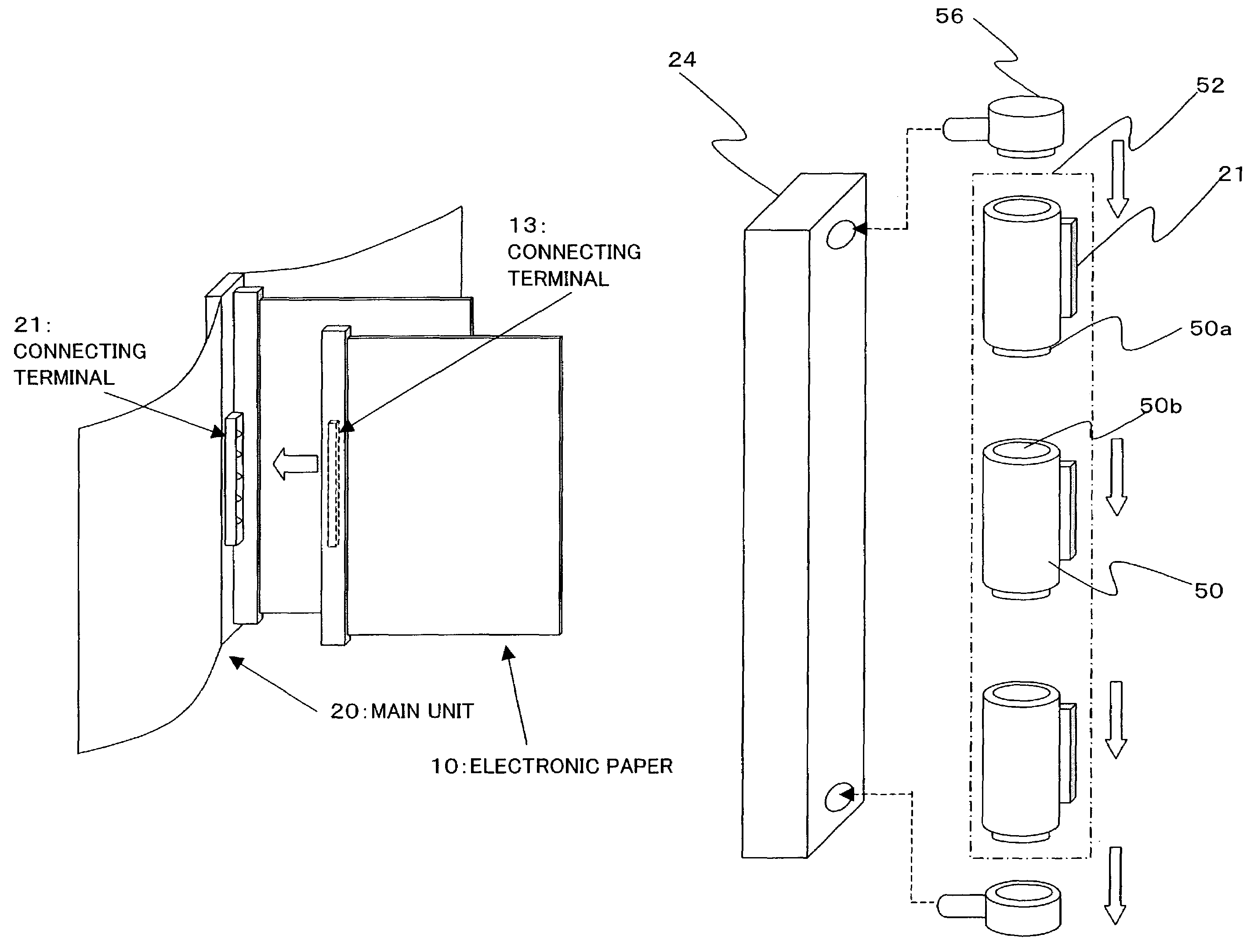
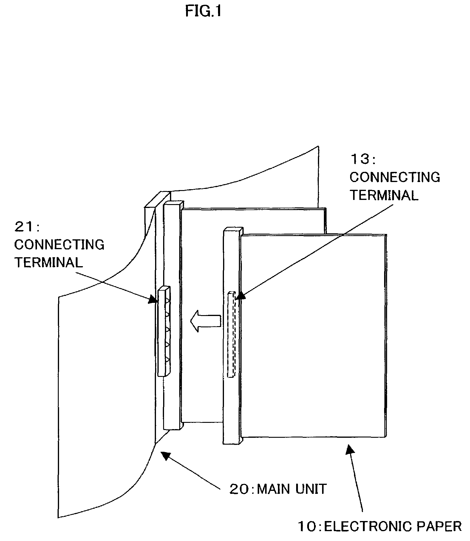
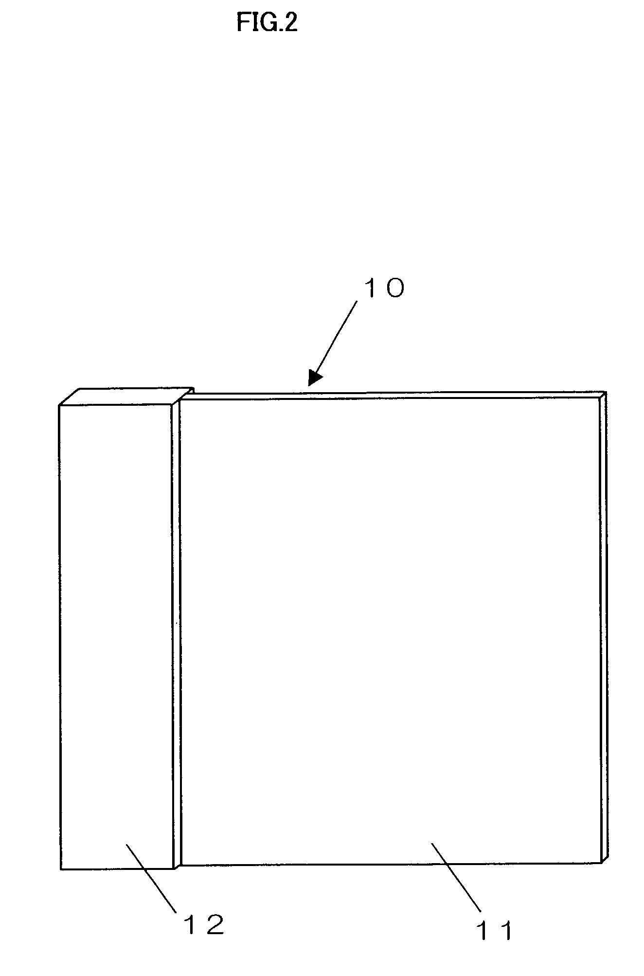
[0072]First of all, the invention in mono color is explained here in detail. FIG. 1 is a perspective view showing the configuration of the invention. FIG. 34 is a block diagram showing the electrical configuration of the invention. FIG. 2 and FIG. 3 are conceptual diagrams showing particulars of the electronic paper.

[0073]As shown in FIGS. 2 and 3, the electronic paper 10 applying the invention comprises a display 11 that is an area for displaying data, and a display driver unit 12 (a data non-display area) for driving the display 11. The display 11 comprises a display layer A provided with a nonvolatile display medium and a luminescence layer B for illuminating the display layer A.

[0074]That is to say, first a column electrode A3 is formed on an upper base film A2, meanwhile, a line electrode A5 is formed on the lower base film A6 as shown in FIG. 4. Secondarily, a ferroelectric high polymer liquid cr...

embodiment 2

[0141]As explained in the embodiment 1, the display luminescence control means 22 is to display the data transmitted from the external or the data stored in the storage medium. Additionally, using the following writing means makes possible that the user be free to write his desired description into the electronic paper 10 or delete his desired description from the electronic paper 10.

[0142]That is to say, as shown in FIG. 24(a) and FIG. 24(b), the column electrode A3 arranged on the back of the base film A2 on the front side of the electronic paper is led to the surface of a deflection plate A1 through a through-hole 100 while being corresponding to each pixel. The column electrode A3 led in such way is connected with an end of switch means 101 through the lead 103 (a contact electrode). And then it is led again to the backside of the base film A2 from the other end of this switch means 101 through the lead 104 and the through-hole 100.

[0143]The switch means 101 is inserted between ...

embodiment 3

[0153]In the above-mentioned embodiment 2, the electronic paper is configured to be suited for performing the direct writing. The digitizer applied to the configuration of the conventional display device is fitted to the electronic paper, and the electronic paper is configured that the writing (the deleting) can be performed according to the position signal outputted from the digitizer. In result, it is possible to perform the writing or the deleting in relative easy. However, installing the digitizer in each electronic paper might increase the cost of the electronic paper. Consequently, the following configuration is possible to put the function of the digitizer to effective use.

[0154]FIG. 27 is a diagram showing the configuration that the writing means comprises a sheet including the digitizer function and a writing material. FIG. 28 is the block diagram. It is arranged that the digitizer can detect the position to which the writing material contacts and the display 11 can be look...


PUM


Abstract

The invention has an object to provide the electronic paper file, which an electronic paper can be attached to or detached from by providing a connecting terminal including the physical or electrical connecting function to both the electronic paper and the main unit. Since the display data is to be displayed on the nonvolatile display medium fitted to the display of the electronic paper, the electronic paper detached from the main unit can retain the display content. Since the connecting terminal fitted to the main unit is fixed to the rotatable rotatable axis, it is possible to retain the desired page with keeping double-pages spread.

Description

TECHNICAL FIELD[0001]The invention relates an electronic paper that is a display medium flexible like paper, and an electronic paper file comprising a plurality of said electronic papers bound like the book.DESCRIPTION OF THE RELATED ART[0002]With the advance of the information society, the performance of the display medium such as CRT (Cathode Ray Tube), LCD (Liquid Crystal Display) and so on has been improved rapidly. However, regarding the legibility and user-facility, such display mediums are not superior to the “paper” that has been used as an information medium from a long time ago. Consequently, the “electronic paper” is proposed as a new concept for the above sheet-like flexible display medium, and the various technologies have been studied in order to carry out this electronic paper (Pages 209 to 251 of “Japan Hardcopy'99—The Collected Papers” published by The Imaging Society in Japan).[0003]Additionally, it is also proposed in these days the electronic paper file filing pl...

Claims


Application Information

Patent Timeline
Patent Type & Authority Patents(United States)
IPC IPC(8): G09G5/00G09F9/37
CPCG06F1/1615G06F1/1647G06F1/1652G06F1/1654G06F1/1677G09F9/372G09G3/34G09G2380/02Y10S345/901G09G3/035
Inventor NAKAMURA, TETSUROHTATEKAWA, MASAICHIROMATSUO, HIROYUKI
Owner PANASONIC CORP
Why Eureka
Try Eureka