Optical apparatus

a technology of optical apparatus and optical lens, applied in the field of optical apparatus, can solve the problems of limited freedom of optical design or mechanical design, limited optical apparatus size, and difficulty in improving the zoom efficiency of the zoom-lens system, so as to reduce the size of the optical apparatus and improve the zoom efficiency

Active Publication Date: 2006-12-26
CANON KK
View PDF3 Cites 6 Cited by
  • Summary
  • Abstract
  • Description
  • Claims
  • Application Information

AI Technical Summary

Benefits of technology

[0007]The present invention is directed to an optical apparatus that provides the structure of a blur-compensating optical system that can contribute to the reduced size of the optical apparatus, and further to improved zoom efficiency when used in a zoom-lens system.

Problems solved by technology

However, when only the compensating lens unit is driven in the orthogonal-to-optical-axis direction, the freedom of optical design or the freedom of mechanical design, which involves the drive mechanisms of the light-quantity-adjusting unit and compensating lens unit, are limited.
This may become an obstacle to the downsizing of optical apparatuses.
It is thus difficult to improve the zoom efficiency in the zoom-lens system.

Method used


Image

  • Optical apparatus
  • Optical apparatus
  • Optical apparatus

Examples


Embodiment Construction

[0018]The embodiments of the present invention will now be described with reference to the drawings.

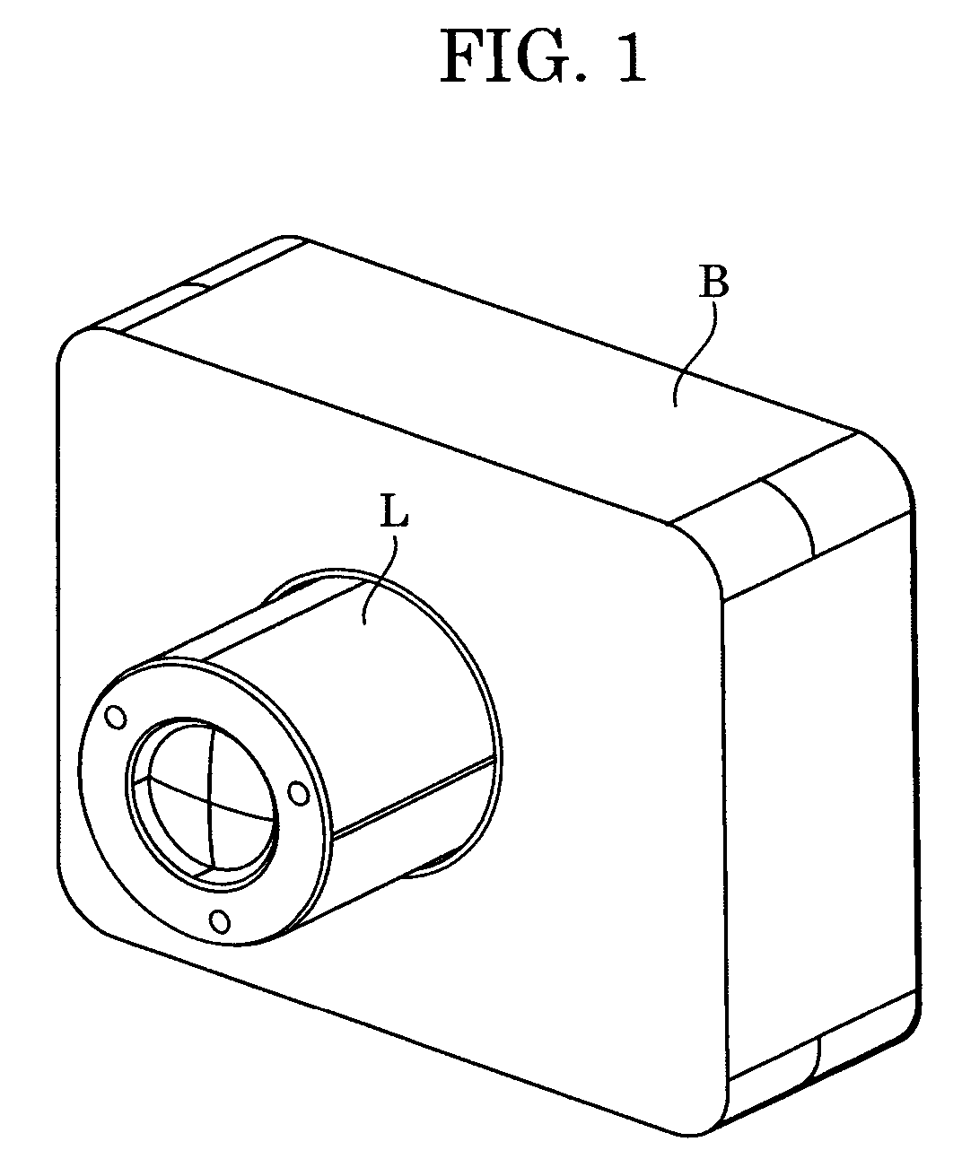
[0019]FIG. 1 shows the structure of an image-capturing apparatus (hereinafter referred to as “camera”), such as a camcorder and a digital camera, according to an embodiment of the present invention. Referring to FIG. 1, the camera includes a lens barrel L with zooming capabilities and a camera body B. The camera body B includes a silver-salt film or an image-capturing device for recording a subject image formed by an image-capturing optical system in the lens barrel L.

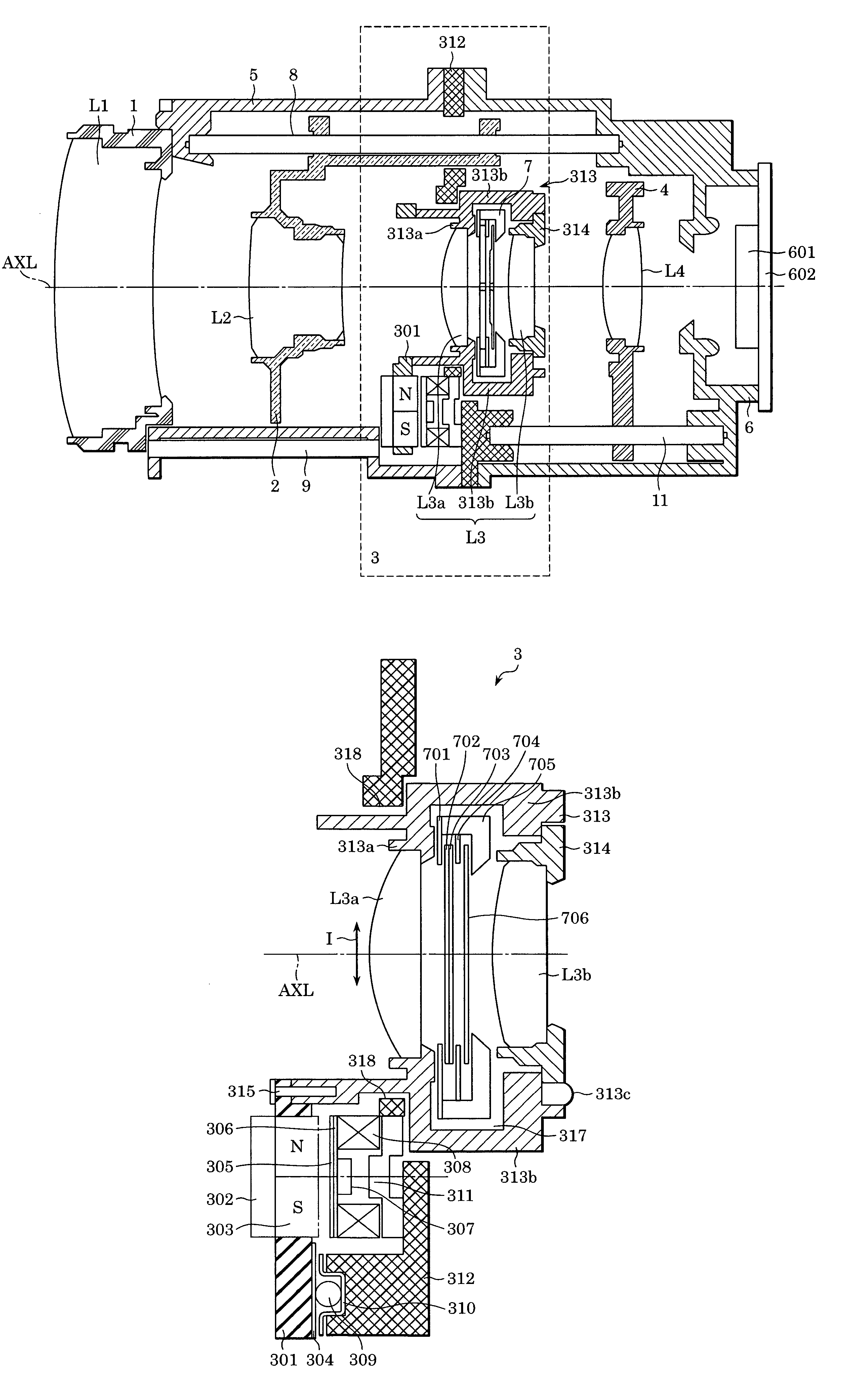
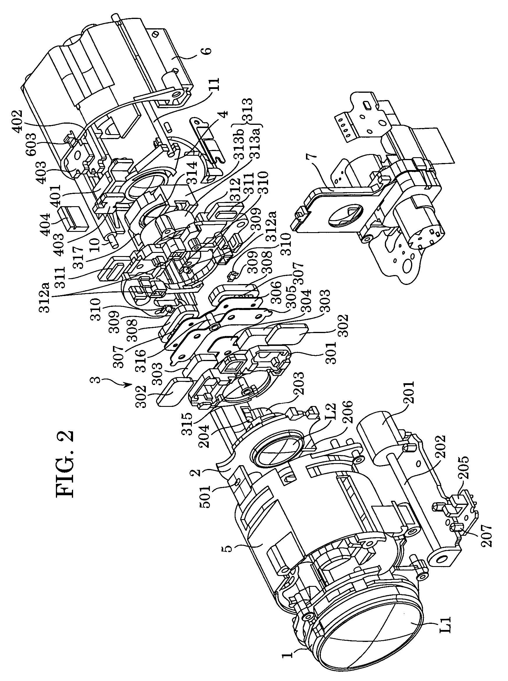
[0020]FIGS. 2 and 3 show the structure of the lens barrel L shown in FIG. 1. The image-capturing optical system is a zoom optical system (zoom lens system) including four lens units, that is, convex, concave, convex, and convex lens units, starting from the object side (from the left in each drawing). FIG. 4 is a cross-sectional view of a shift unit 3 serving as a blur-compensating device included in the lens barrel L.

[0...


PUM


Abstract

An optical apparatus includes a light-quantity-adjusting unit, a first lens unit disposed closer to an object than the light-quantity-adjusting unit, a second lens unit disposed closer to an image plane than the light-quantity-adjusting unit, and a drive unit for driving the first lens unit and the second lens unit in an orthogonal-to-optical-axis direction.

Description

BACKGROUND OF THE INVENTION[0001]1. Field of the Invention[0002]The present invention relates to optical apparatuses, such as image-capturing apparatuses including camcorders and digital still cameras, and interchangeable lens systems.[0003]2. Description of the Related Art[0004]Image-capturing apparatuses and interchangeable lens systems often include a blur-compensating device for moving a lens in a direction substantially orthogonal to the optical axis (hereinafter, referred to as “orthogonal-to-optical-axis direction”) to bend the optical axis of the image-capturing optical system, thereby compensating for image blur caused by hand movement or the like. Generally, in such a blur-compensating device, a lens unit closer to the image plane (hereinafter referred to as “compensating lens unit”) than a light-quantity-adjusting unit is driven in the orthogonal-to-optical-axis direction (see Patent Document 1: Japanese Patent Laid-Open No. 7-36074, corresponding to U.S. Pat. No. 5,715,4...

Claims


Application Information

Patent Timeline
Patent Type & Authority Patents(United States)
IPC IPC(8): G02B27/64G02B7/10G02B15/00G02B15/14G02B15/16G03B5/00H04N5/225
CPCG02B15/00G02B15/14G02B27/646H04N5/23258H04N5/23287G02B15/144H04N23/6812H04N23/687
Inventor UMEZU, TAKUJINOGUCHI, KAZUHIRO
Owner CANON KK
Why Eureka
Try Eureka