
Low cost squib driver for airbag application

a low-cost, airbag-type technology, applied in the field of electronic circuits, can solve the problems of enlarge the unwanted power dissipation within the integrated power circuit, premature destruction of said semiconductor switching devices, and damage to the harness, and achieve the effect of low cos

Inactive Publication Date: 2006-12-26
DIALOG SEMICONDUCTOR GMBH
View PDF16 Cites 18 Cited by
  • Summary
  • Abstract
  • Description
  • Claims
  • Application Information

AI Technical Summary

Benefits of technology

"The present invention is a driver device for igniters or squibs that is very efficient, low-cost, and can be easily integrated into integrated circuits. The device can be operated with a single integrated circuit and can securely and reliably control the firing of the igniters or squibs. The device includes secure and continuous surveillance of the ignition devices and electronic switching devices, as well as economizing the floor space needed for the integrated circuit. The device also includes diagnostic test mechanisms and online testing features for circuit protection and operation securing purposes. The invention is a new method for the controlled operation and secure firing of igniters or squibs, which can reduce the cost of the system and minimize power consumption. The invention also includes a new method for measuring the resistance of the electronic switches and squibs, and a new method for driving the high-side and low-side switching devices. The invention can reduce the cost of manufacturing and the number of expensive components."

Problems solved by technology

It is conceivable that eventually some portion of the harness might become damaged, i.e. short to ground (GND) or even to the AVS voltage.
Preferred prior art circuits obeying to automotive industry regulations do not allow a direct galvanic connection of the squib to the supply voltages—neither to the AVS voltage nor to GND voltage with possible firing current flowing—during normal operation of the vehicle, i.e. not firing the squib, and therefore include two separate switches on every side of a squib.
Due to supply voltage variations and deviations from the normal squib resistance from about 2 Ohms the current through the switches may vary between approximately 2 A and 4.5 A. For integrated squib power transistor switches however the current flowing through these switching devices must be limited to approximately 3 A, therefore it has to be measured and limited during said firing operation and additionally the transistors must be forced to reduce their on-resistance to avoid excessive power dissipation, which could lead to a premature destruction of said semiconductor switching devices.
The current practice of sensing this current with resistors causes excess voltage drop that in consequence enlarges the unwanted power dissipation within the integrated power circuit.
This disadvantage poses a major problem for that sort of circuits.
In daily use of these circuits in vehicles and especially under all the existing environmental conditions appearing on earth during operation of an automobile another major problem is the degradation of the devices during lifetime and therefore a multitude of techniques and methods for their implementations has been specified in the past.
The main problem hereby is due to the fact, that in most cases the known prior art solutions are very elaborate and complicated when all the requirements as established by the automotive industry have to be met, thereby giving practical realizations leading to very costly devices.
It is therefore a challenge for the designer of such devices and circuits to achieve a high-quality and also low-cost solution.

Method used


Image

  • Low cost squib driver for airbag application
  • Low cost squib driver for airbag application
  • Low cost squib driver for airbag application

Examples


Embodiment Construction

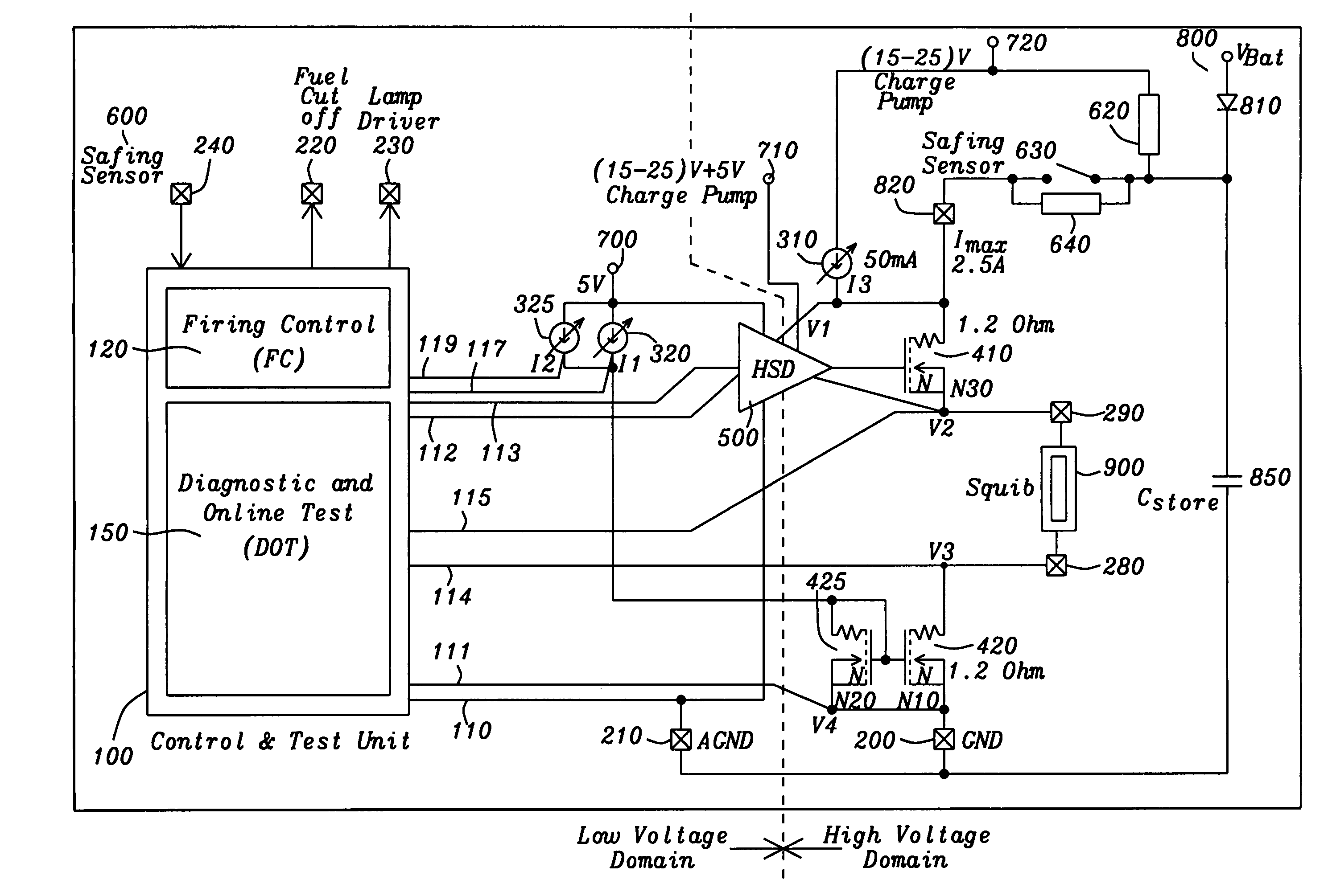
[0041]The preferred embodiments disclose a novel optimized circuit conception for a squib driver using modern integrated digital circuits and an exemplary circuit thereto.

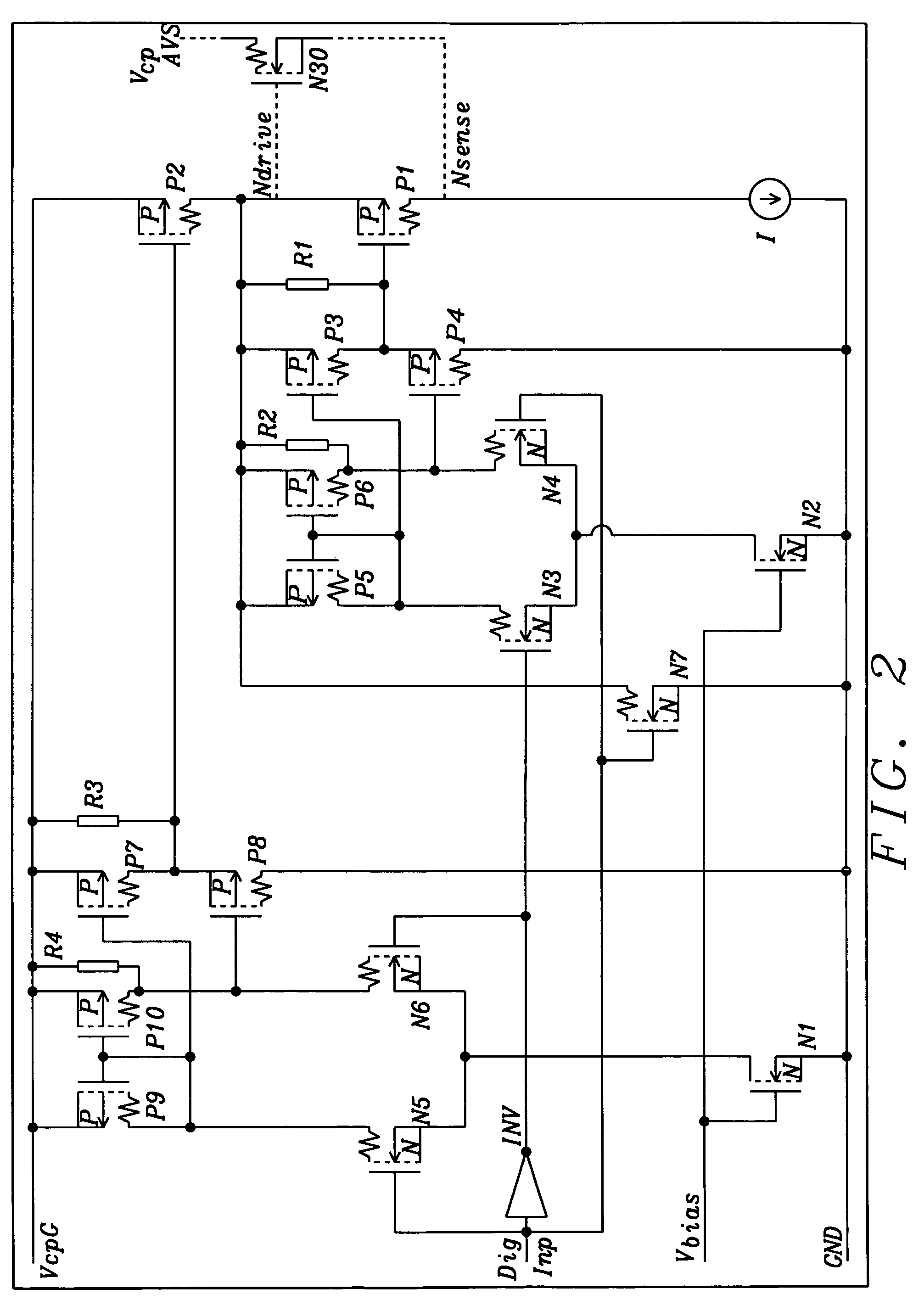
[0042]The description of the preferred embodiments of the invention is subdivided into two parts; first an overall description of the whole implementation and its conceptional design is given and second a detailed description of an incorporated driver circuit part is presented, which is called High-Side Driver (HSD) and forming an essential part of the invention.

[0043]The approach for driving squibs within SIR systems implemented here is to some extent already known and has therefore been described in detail in the prior art description section above. Its in-depth comprehension is indeed a prerequisite for the understanding of the following new circuit approaches and design principles.

[0044]Important and valid are the respective automotive industry regulations, which do not allow during normal operation of the vehi...


PUM


Abstract

A circuit and a method are given, to realize a very efficient driver device for igniters or squibs as used e.g. in airbag applications. Special attention has been turned to include secure and always reliable operating features into the device and at the same time to reach for a low-cost implementation with modern integrated circuit technologies. Controlled firing operation and sophisticated diagnostic mechanisms are realized. These design features have been acquired by use of current mirror circuit principles for the switching devices where appropriate and with special regard to production cost. Current trimming and limitation to secure values are part of the solution.

Description

RELATED PATENT APPLICATION[0001]This application is related to U.S. patent application Ser. No. 10 / 828,889, filed concurrently, and assigned to the same assignee as the present invention. Title: “Squib Driver for Airbag Application”BACKGROUND OF THE INVENTION[0002](1) Field of the Invention[0003]The present invention relates in general to electronic circuits as used within Supplemental Inflatable Restraint (SIR) systems for automotive vehicles and the like, and, more specifically, to semiconductor integrated driver circuits which are employed in such automobile airbag systems for deploying airbags using igniters or squibs; and including a firing control section guaranteeing secure operation under any circumstances and also including circuit diagnostics for testing the proper operation capabilities of the drivers that supply the electrical energy to ignite the squibs.[0004](2) Description of the Prior Art[0005]The main components of Supplemental Inflatable Restraint (SIR) systems for...

Claims


Application Information

Patent Timeline
Patent Type & Authority Patents(United States)
IPC IPC(8): F23Q5/00F23Q7/00B60R21/01
CPCB60R21/0173
Inventor SIBRAI, ANDREAS
Owner DIALOG SEMICONDUCTOR GMBH
Learn More