Multi-carrier transmission system and associated method of reducing the effect of multi-path interference

a multi-carrier transmission system and interference reduction technology, applied in the field of transmission systems, transmission methods, transmission apparatuses, electronic recording mediums, can solve the problems of affecting the receiving performance of radio signals at the receiver, affecting the accuracy of path timing detection for respective paths, and the level of rake time-diversity effect tending to get saturated or decrease, so as to reduce the effect of mpi and high signal quality

Inactive Publication Date: 2006-12-26
NTT DOCOMO INC
View PDF4 Cites 16 Cited by
  • Summary
  • Abstract
  • Description
  • Claims
  • Application Information

AI Technical Summary

Benefits of technology

[0016]The present invention has been made in view of the above problems, and thus has an object to provide a transmission system, transmission method, transmission apparatus, and electronic recording medium having recorded therein a transmi...

Problems solved by technology

However, in an actual environment, in a case where large numbers of the multipath signals are observed due to expansion of the radio bandwidth, a multipath interference (hereinafter referred as MPI) which the respective signals interfere each other at the receiving unit occurs.
Due to the MPI, signal power per path decreases and it causes that the accuracy of the path timing detection for respective paths becomes deteriorated.
Moreover, the accuracy of channel estimation, which estimates volume of a fluctuation occurred on the radio link based to the detected signal, becomes deteriorated accordingly and it affects the receiving performance of the radio signal at the receive...

Method used


Image

  • Multi-carrier transmission system and associated method of reducing the effect of multi-path interference
  • Multi-carrier transmission system and associated method of reducing the effect of multi-path interference
  • Multi-carrier transmission system and associated method of reducing the effect of multi-path interference

Examples


first embodiment

[First Embodiment]

[0031]Outline of the Transmission Method

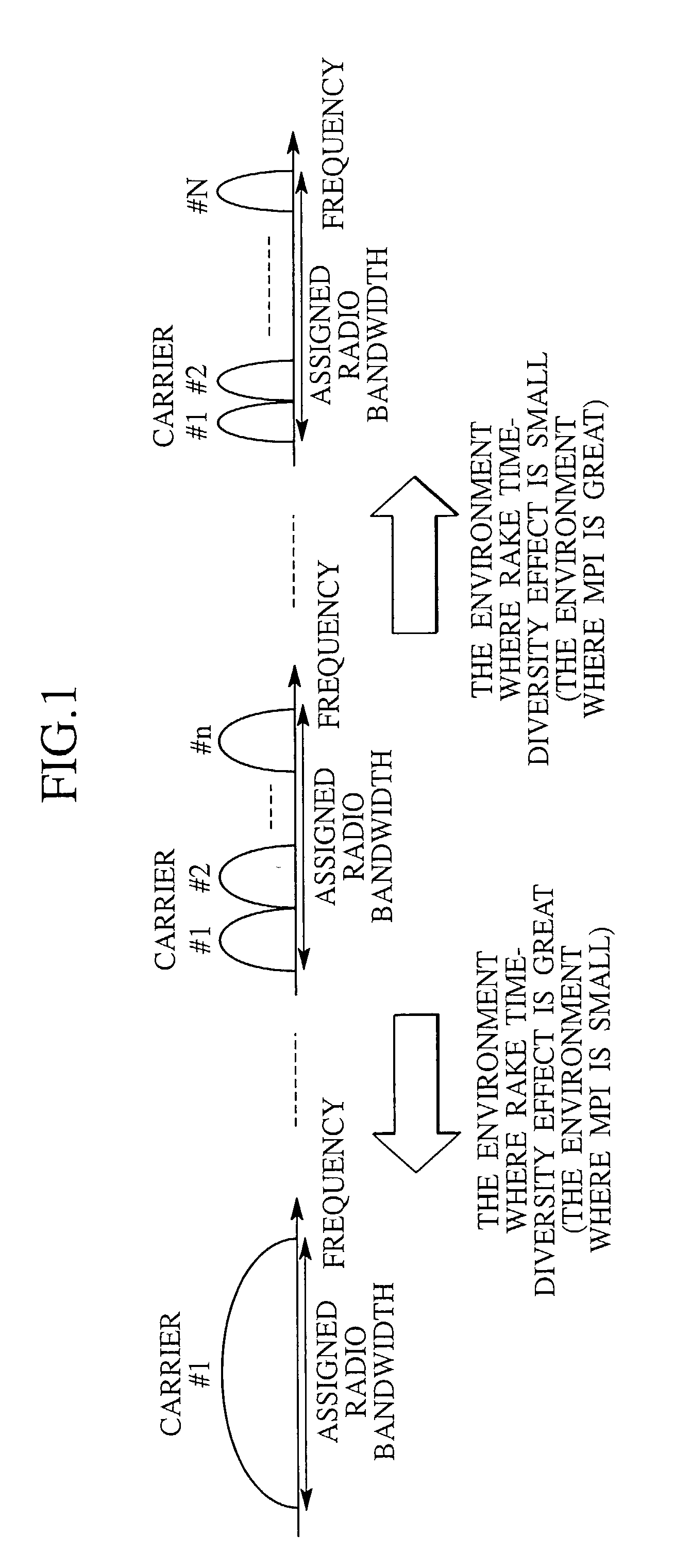
[0032]Hereinafter, an embodiment of the transmission method according to the present invention will be described. FIG. 1 shows the concept of the transmission method according to this embodiment. The frequency spectrums of DS-CDMA signals which are transmitted by an “n” pieces of parallel carriers are shown in FIG. 1.

[0033]The transmission method according to this embodiment is applied in a case where transmitting a plurality of signals using a plurality of carriers between the transmitting apparatus and the receiving apparatus, and the number of carriers is determined based on estimation of characteristics of a radio link between the transmitting apparatus and the receiving apparatus. Here, the number of carriers is decreased when the MPI is small and, the number of carriers is increased when the MPI is great.

[0034]Specifically, as shown in FIG. 1, the transmitting apparatus performs serial-to-parallel conversion of a serial...

second embodiment

[Second Embodiment]

[0048]Configuration of Transmission System

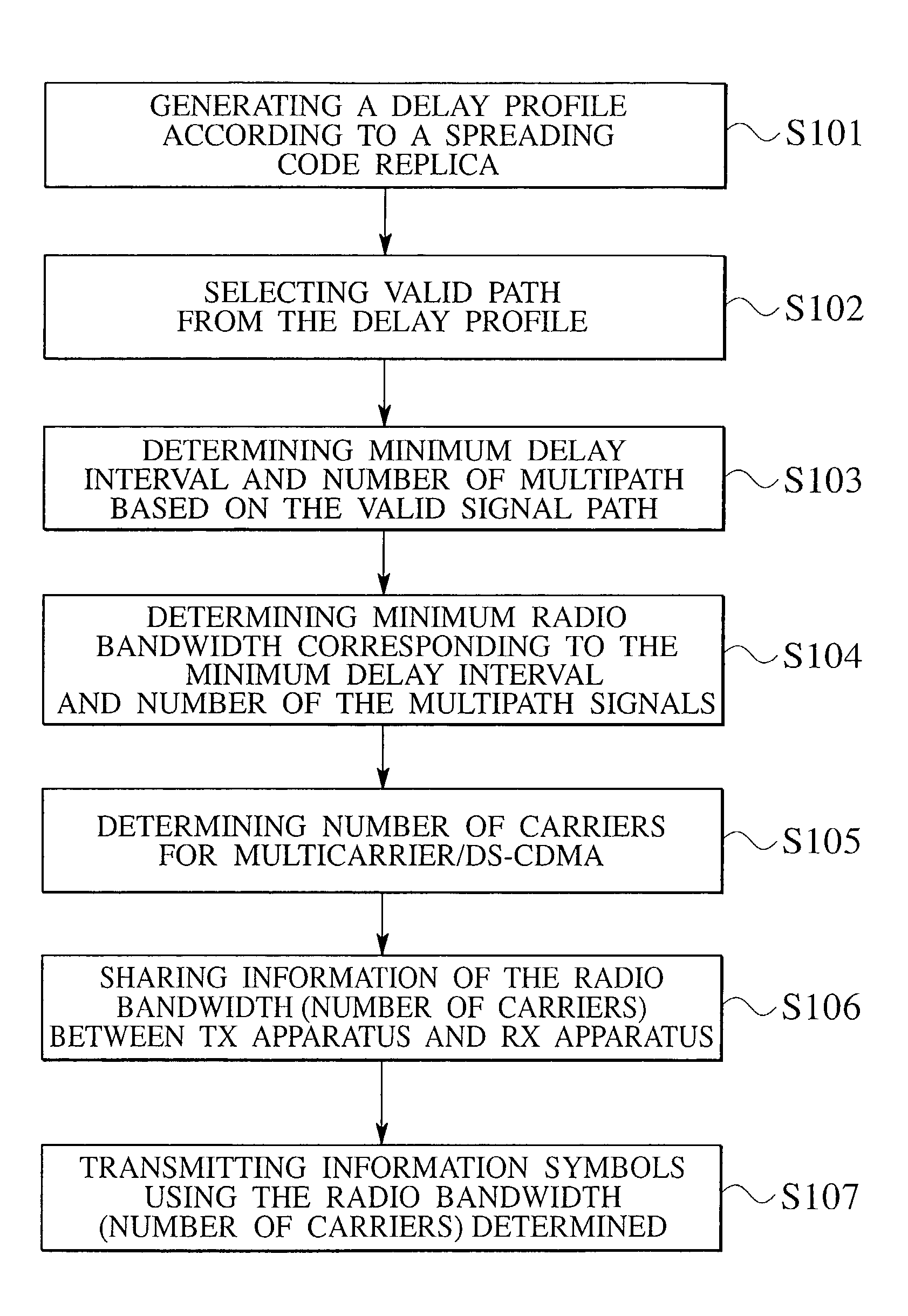
[0049]A second embodiment of the present invention will be described below. In the transmission system of the second embodiment, the receiving apparatus receives a spread signal which has been spread by a spreading code, and despreads the received signal whose timing is shifted. The receiving apparatus generates a delay profile based on a result of the despreading process and selects a path satisfying a prescribed condition according to the delay profile. The receiving apparatus then determines the number of carriers according to the path that has been selected.

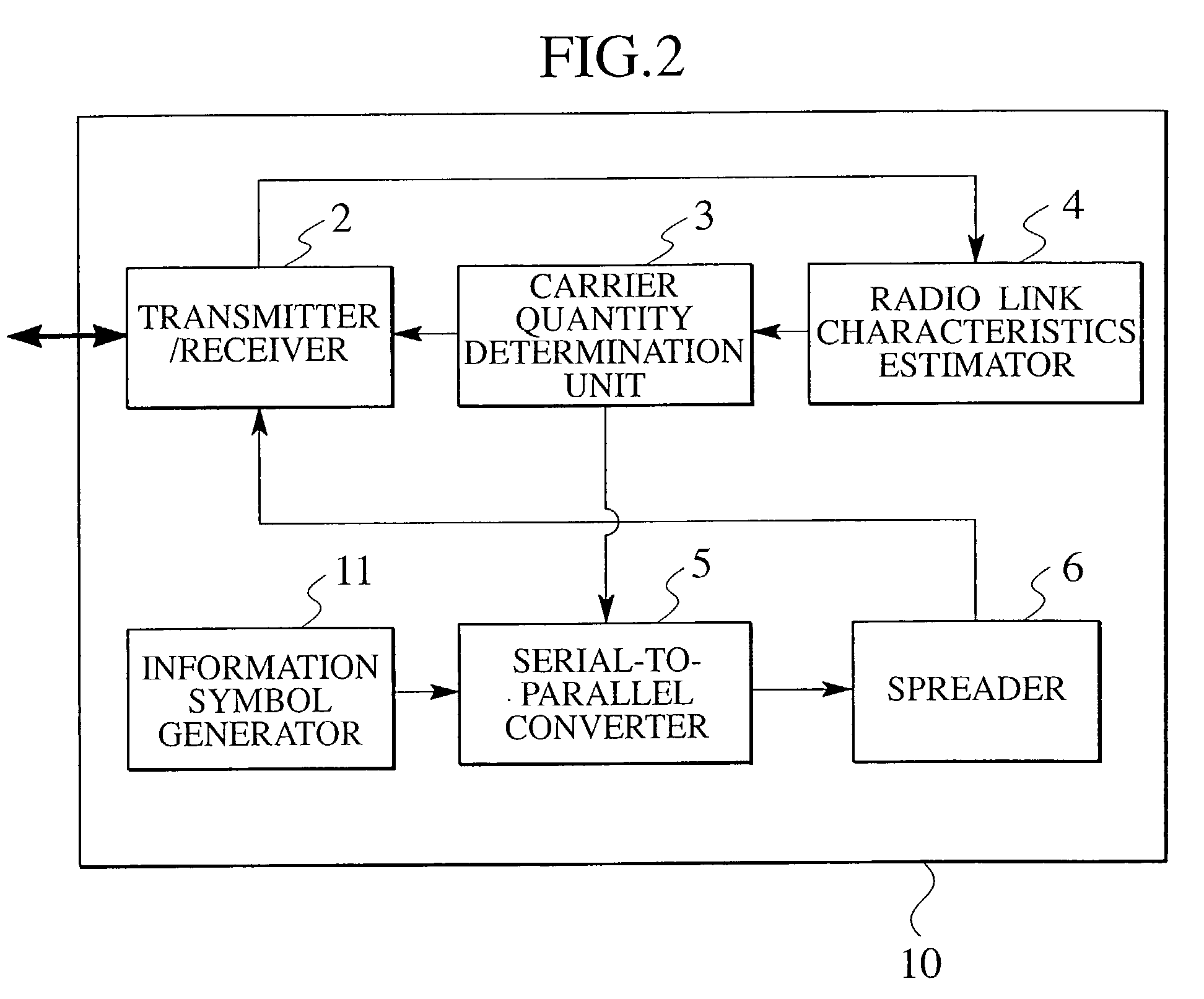
[0050]FIG. 3 is a block diagram showing the configuration of a receiving apparatus 20 for the transmission system of this embodiment. As shown in the figure, the receiving apparatus 20 comprises a transmitter / receiver 2, a carrier quantity determination unit 3, a radio link characteristics estimator 4, a delay profile generator 7, a valid path selector 8, a carrier ...

third embodiment

[Third Embodiment]

[0070]Configuration of Transmission System

[0071]A third embodiment of the present invention will be described below. The third embodiment has feature of estimating the characteristics of the radio link, which has been described in the second embodiment, on a periodic basis. FIG. 5 is a block diagram showing a receiving apparatus 30 of the third embodiment.

[0072]The receiving apparatus 30 of this embodiment further comprises a timer 34 in addition to the receiving apparatus 20. The timer 34 sends a control signal to the delay profile generator 7 on a periodic basis, and can thereby trigger the delay profile generator 7 to generate a delay profile at certain intervals. The delay profile generated by the delay profile generator 7 is forwarded to the valid path selector 8. Thereby, the characteristics of the radio link are periodically estimated.

[0073]Process of Transmission System

[0074]The receiving apparatus 30 which has the above configuration operates according to ...


PUM


Abstract

The transmission system of the present invention is designed to transmit a plurality of signals between the transmitter and the receiver using a plurality of carriers and comprises a radio link characteristics estimator 4 configured to estimate the characteristics of a radio link between the transmitter and the receiver and a carrier quantity determination unit 3 configured to determine the number of carriers according to the result of the estimate by the radio link characteristics estimator 4. The radio link characteristics estimator 4 estimates the characteristics according to an interval in delay time of multipath signals and the number of the multipath signals. The carrier quantity determination unit 3 determines fewer carriers when multipath interference is small, and determines more carriers when the multipath interference is great.

Description

CROSS REFERENCE TO RELATED APPLICATIONS[0001]This application is based upon and claims the benefit of priority from the prior Japanese Patent Applications No. P200-345171, filed on Nov. 9, 2001; the entire contents of which are incorporated herein by reference.BACKGROUND OF THE INVENTION[0002]1. Field of the Invention[0003]The present invention relates to a transmission system, transmission method, transmission apparatus, and electronic recording medium having recorded therein a transmission program, which are configured to transmit a plurality of signals using a plurality of carriers between the transmitter and the receiver, for example, a multicarrier / DS-CDMA.[0004]2. Description of the Related Art[0005]The wideband code division multiple access (W-CDMA) and the cdma2000 have been adopted as the method of a radio access for the 3rd generation mobile telecommunications system (IMT-2000). The radio bandwidth per carrier is 5 MHz for the W-CDMA, and is 1.25 MHz for the cdma2000.[0006...

Claims


Application Information

Patent Timeline
IPC IPC(8): H04L27/28H04J1/02H04B1/707H04B1/711H04B7/26H04L5/02H04L25/02H04L27/26H04W16/28H04W28/18
CPCH04L5/026H04L25/0216H04L25/0236H04B1/7115H04B1/7117H04B7/26
Inventor SUWA, SHINGOATARASHI, HIROYUKIABETA, SADAYUKISAWAHASHI, MAMORU
Owner NTT DOCOMO INC
Why Eureka
Try Eureka