Receiving apparatus and synchronizing method for a digital telecommunication system

a technology of receiving apparatus and digital telecommunication system, which is applied in the direction of mechanical apparatus, synchronisation signal speed/phase control, operating means/releasing devices of valves, etc., can solve problems such as synchronization failure, and achieve the effect of improving synchronization performance and accuracy

Inactive Publication Date: 2006-12-26
REDWOOD TECHNOLOGIES LLC +1
View PDF9 Cites 25 Cited by
  • Summary
  • Abstract
  • Description
  • Claims
  • Application Information

AI Technical Summary

Benefits of technology

[0014]The object of the present invention is therefore to provide a receiving apparatus for receiving signals in a digital telecommunication and a synchronising method for synchronising a receiving apparatus in a digital telecommunication system, which provide an improved synchronisation performance and accuracy.
[0018]The receiving apparatus and the synchronising method of the present invention thereby provide an improved cross correlation performance for time and frequency synchronisation, particularly accurate information on the synchronisation timing. The present invention is especially efficient for synchronisation in a mobile telecommunication environment in which multipath fading degrades the synchronisation performance and accuracy. The receiving apparatus and synchronising method of the present invention are applicable to single carrier systems as well as multicarrier systems, e.g. OFDM (Orthogonal Frequency Division Multiplexing) systems.
[0019]Advantageously, said at least two repetition patterns are the last two repetition patterns in the reference symbol. It is to be noted, that the synchronising mechanism of the present invention only requires two repetition patterns. Since the two repetition patterns are phase shifted in relation to each other, accurate information on the synchronisation time point can be achieved by observing the cross correlation peak and the relative phase of the cross correlation peak. However, more than two repetition patterns enhance the performance. Advantageously, the phase shifted repetition pattern is phase shifted by 180° in relation to the other repetition pattern. Thereby a very accurate and reliable phase detection is possible.
[0020]Advantageously, the phase change information of the two repetition patterns in the reference symbol is used in the synchronising means to detect a cross correlation peak which indicates the position of the later one of said repetition patterns. The correlation peak information is calculated using the phase change information of the two repetition patterns, which allows an accurate and reliable detection of the correlation peak position and thus the synchronisation time point.
[0022]According to another aspect of the present invention, the cross correlation means has a cross correlation window length corresponding to the length of two repetition patterns for detecting the position of the cross correlation peak. The cross correlation means of the further aspect of the present invention thus directly cross correlates received data signals on the basis of the length of two repetition patterns, which leads to a more complex structure of the cross correlation means, but enables a more effective and sophisticated synchronising mechanism. In the cross correlation means according to the further aspect, the stored positive and the negative conjugation of the expected repetition pattern can be used for detecting the position of the cross correlation peak.
[0025]Using the peak threshold detection means and the gap detection means, additional criteria are checked to increase the synchronisation performance and reliability.

Problems solved by technology

On the other hand, if one of the cross correlation peaks is not properly detected, the synchronisation fails.

Method used


Image

  • Receiving apparatus and synchronizing method for a digital telecommunication system
  • Receiving apparatus and synchronizing method for a digital telecommunication system
  • Receiving apparatus and synchronizing method for a digital telecommunication system

Examples


first embodiment

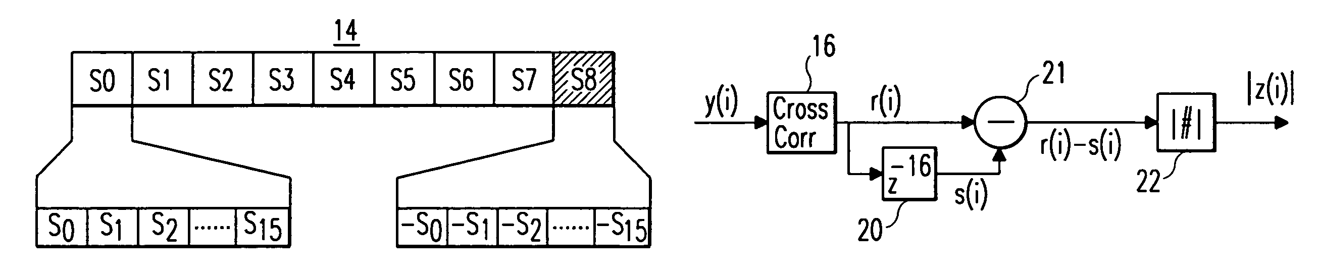
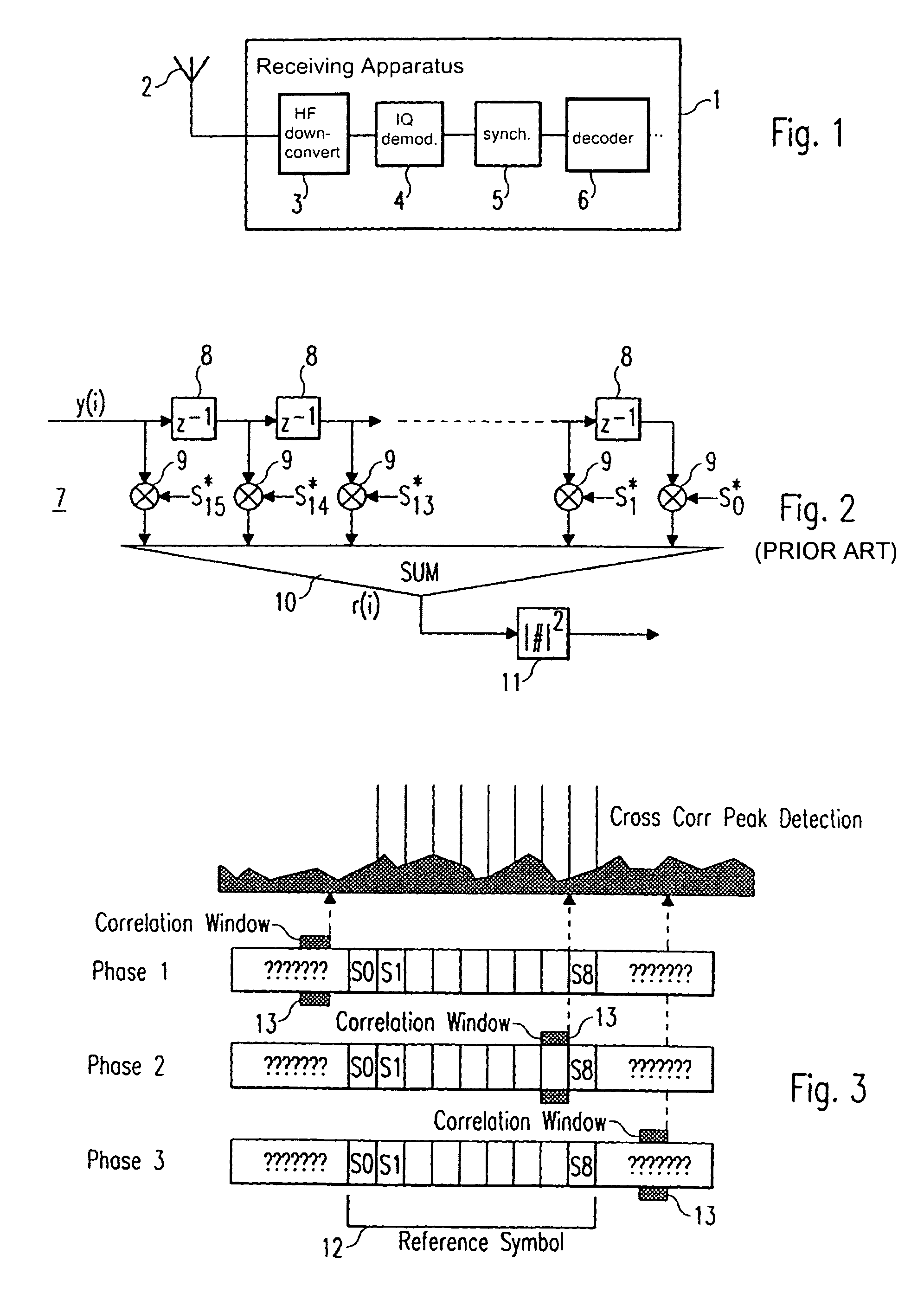
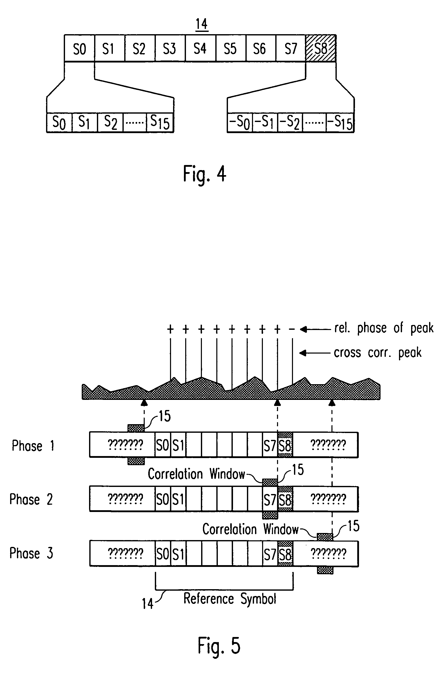
[0044]In FIG. 6, a cross correlation means 16 and a detection means 19 are shown, which can be implemented in a synchronising means 5 of a receiving apparatus 1 of the present invention, the general structure of which is shown in FIG. 1. The structure of the cross correlation means 16 is identical to the structure of the cross correlation means 7 shown in FIG. 2, so that a detailed explanation is omitted. The cross correlation means 16 comprises 15 delay means 17 and 16 multiplication means 18 as well as a sum means for adding the outputs of the multiplication means 18. The cross correlation window length of the cross correlation means 16 corresponds to the length of one repetition pattern, which is e.g. 16 samples. A received data stream of 16 samples is cross correlated with complex conjugated samples of an expected repetition pattern stored in the receiving apparatus 1. The output signal r(i) of the sum means, i.e. the output signal of the cross correlation means 16 is supplied t...

second embodiment

[0051]In FIG. 11, a cross correlation means 24 is shown, which can be implemented in a synchronising means 5 of a receiving apparatus 1 of the present invention, a general structure of which is e.g. shown in FIG. 1.

[0052]The cross correlation means 24 essentially has the same structure as the cross correlation means 16 shown in FIG. 6 and the cross correlation means 7 shown in FIG. 2. The main difference is, that the cross correlation means 24 shown in FIG. 11 has a cross correlation window length of two repetition patterns, which in the shown example corresponds to 32 samples, when the structure of the reference symbol shown in FIG. 4 is assumed. Thereby, the cross correlation means 24 comprises 31 delay means 25, which are arranged serially and respectively cause a delay of one sample. Further, the cross correlation means 24 comprises 32 multiplication means, which multiply the respective (delayed) samples of the received signal y(i) with stored positive and negative complex conju...


PUM


Abstract

A receiving apparatus (1) for receiving signals in a digital telecommunication system and a synchronizing method for synchronizing the receiving apparatus (1). The receiving apparatus (1) includes a receiver (2, 3) for receiving a reference symbol having at least two repetition patterns. One of the repetition patterns is phase-shifted in relation to the other. The receiving apparatus (1) is synchronized in the digital telecommunication system using the received reference symbol. The synchronization includes a cross correlation of at least one of the two repetition patterns within a cross correlation window having a predetermined length. In this manner, the performance and the accuracy of a cross correlation peak detection can be enhanced for improved synchronization.

Description

BACKGROUND OF THE INVENTION[0001]The present invention relates to a receiving apparatus for receiving signals in a digital telecommunication system and to a synchronising method for synchronising such a receiving apparatus. Particularly, the receiving apparatus and the synchronising method of the present invention use a cross correlation mechanism to achieve accurate time and frequency synchronisation.[0002]Digital telecommunication systems generally need a synchronisation of a transmitting side and a receiving side. The transmitting side and the receiving side can e.g. be base stations and mobile stations of a telecommunication system, whereby the synchronisation of the timing and the frequency of transmitted signals is usually performed in the mobile station. To achieve a synchronisation, it is known to transmit a special training sequence or a reference symbol. Such a reference symbol is usually embedded in the transmission data structure and regularly sent so that a synchronisat...

Claims


Application Information

Patent Timeline
Patent Type & Authority Patents(United States)
IPC IPC(8): H04L25/38H04L7/08H04B7/26H04L7/00H04L7/04
CPCH04L7/041H04L7/046F16K37/0041F16K3/02F16K31/53
Inventor BOHNKE, RALFDOLLE, THOMASKONSCHAK, TINO
Owner REDWOOD TECHNOLOGIES LLC
Why Eureka
Try Eureka