Interconnection routing method

a technology of interconnection routing and semiconductor chips, applied in the direction of instruments, computing, electric digital data processing, etc., can solve the problems of multiple coupling problems, affecting the accuracy of noise metric evaluation, so as to prevent overflow of noise metric, the effect of rapid acquisition of noise metri

Inactive Publication Date: 2006-12-26
TAIWAN SEMICON MFG CO LTD
View PDF5 Cites 1 Cited by
  • Summary
  • Abstract
  • Description
  • Claims
  • Application Information

AI Technical Summary

Benefits of technology

[0013]An advantage of the present invention is to accurately and simultaneously evaluate a noise metric between a victim connection path and an aggressor connection path while placing the victim connection path. Thus addressing crosstalk by preventing overflow of the noise metric.
[0014]A further advantage of the present invention is that the noise metric can be rapidly obtained. The noise metric of the next connection path can be determined quickly by effective information comparison, as nearly all parameters and corresponding noise metrics are recorded in a coupling noise database. Thus the total routing time is substantially reduced.
[0015]The following detailed description is given by way of example and not intended to limit the invention solely to the embodiments described herein.

Problems solved by technology

Coupling between routing wires, known as crosstalk, can cause functional failures and timing degradation in a semiconductor integrated circuit.
Increased clock speed and reduced voltage supply in modern designs further worsen the problem.
In modern high density chip design, however, there may be numerous coupling issues found after the first placement and routing.
The manual repair process is difficult and time-consuming.
Additionally, repair of some nets may cause other nets to develop problems.
In a worst-case scenario, there may be insufficient routing resources left to address all the issues.
The effect, however, is limited due to lack of coupling data during the placement stage.
This method, however, is unable to ensure the prevention of crosstalk.
This method is equally incapable of guaranteeing that crosstalk will not occur.

Method used


Image

  • Interconnection routing method
  • Interconnection routing method
  • Interconnection routing method

Examples


Embodiment Construction

[0020]A detailed description of the present invention is provided in the following.

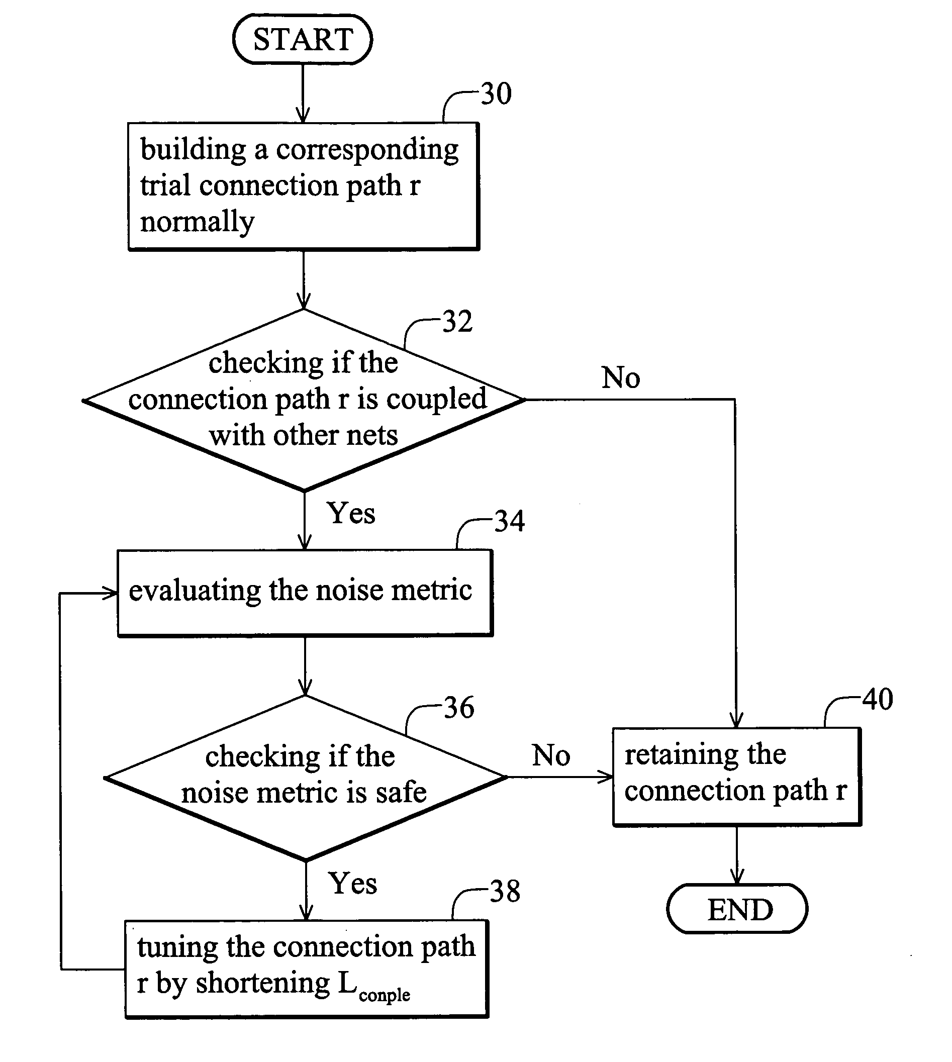
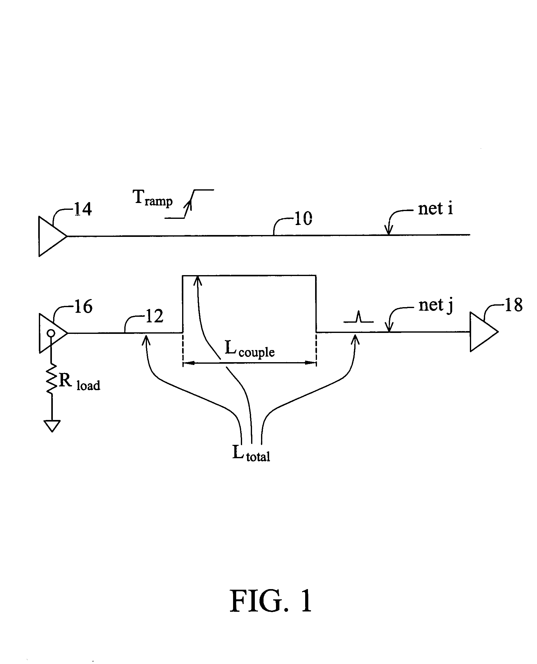
[0021]The object of the present invention is to evaluate noise metrics which a victim connection path might receive through at least four parameters (aggressor signal transition time Tramp, victim net total length Ltotal, coupled wire length Lcoupled, and equivalent load Rload). Thus making the noise metrics low enough to be acceptable by modifying the victim connection path.

[0022]FIG. 1 is an illustration of the four parameters used according to the present invention. In the process of routing, connection paths are placed and routed one by one corresponding to the requirements of each net. There is high possibility that a newly placed connection path will have crosstalk with previously placed paths, hence the newly placed connection path is also designated as a victim, and the previous path an aggressor. In FIG. 1, the aggressor connection path 10 is placed according to the requirements of the net i,...


PUM


Abstract

The present invention relates to a method of interconnection routing for preventing crosstalk. The method comprises the following steps. Providing an aggressor connection path as a first net. Providing a victim connection path according to the requirements of a second net. Determining a voltage ramp time of the aggressor connection path, a victim total length of the victim connection path, a coupled wire length between the aggressor connection path and the victim connection path, and an equivalent load corresponding to the victim connection path. Evaluating a noise metric according to the voltage ramp time, the victim total length, the coupled wire length and the equivalent load. Modifying the victim connection path to shorten the coupled wire length if the noise metric is greater than a pre-determined value. Finally designating the victim connection path as the second net if the noise metric is less than the pre-determined value.

Description

BACKGROUND OF THE INVENTION[0001]1. Field of the Invention[0002]The present invention relates to a method of interconnection routing for semiconductor chips, and more particularly to a method for preventing crosstalk by routing and evaluating the degree of crosstalk simultaneously.[0003]2. Description of the Related Art[0004]The connection path between components in a semiconductor integrated circuit has decreased with increased component quantity. Coupling between routing wires, known as crosstalk, can cause functional failures and timing degradation in a semiconductor integrated circuit. Crosstalk is more severe in deep sub-micron technologies, where neighboring wire coupling capacitance dominates the total net capacitance. Increased clock speed and reduced voltage supply in modern designs further worsen the problem.[0005]Traditionally, to determine if a chip implementation will suffer from crosstalk, a circuit simulation is performed or a static analysis tool is run after placeme...

Claims


Application Information

Patent Timeline
Patent Type & Authority Patents(United States)
IPC IPC(8): G06F17/50
CPCG06F17/5077G06F30/394
Inventor CHEN, BIH-CHERNGHUANG, HSING-CHIEN
Owner TAIWAN SEMICON MFG CO LTD
Why Eureka
Try Eureka