Tubular structure and modular building assembly using the same

a tubular structure and modular technology, applied in the direction of girders, joists, trusses, etc., can solve the problems of affecting the efficiency of assembly, and difficult to maintain heat isolation at the beam and pillar connection sections

Inactive Publication Date: 2007-01-02
LEE DAE JUN
View PDF11 Cites 35 Cited by
  • Summary
  • Abstract
  • Description
  • Claims
  • Application Information

AI Technical Summary

Benefits of technology

[0005]To solve the above problems, it is an object of the present invention to provide a tubular structure which can be applied to a pillar or a beam that is comprised of a plurali...

Problems solved by technology

However, the manufacturing of the existing pillar and beam structures is a complicated construction process.
That is, the manufacturing of the pillars and beams from respective connection portions requires a welding of the portions together, which impedes an efficient assembly.
Also, it is not easy to maintain heat isolation at the beam and pillar connection sections.
As a result, it is very difficult to prevent a moisture formation and to maintain a refractory performance.
In the case where the structure itself is large in size, it is difficult to transport the I-beam structure because it may be damaged during transportation, and a somewhat difficult welding job may be required during construction on site, which causes a difficult construction.
Further, it is expensive to purchase pillar and beam structures and assembly components ther...

Method used


Image

  • Tubular structure and modular building assembly using the same
  • Tubular structure and modular building assembly using the same
  • Tubular structure and modular building assembly using the same

Examples


first embodiment

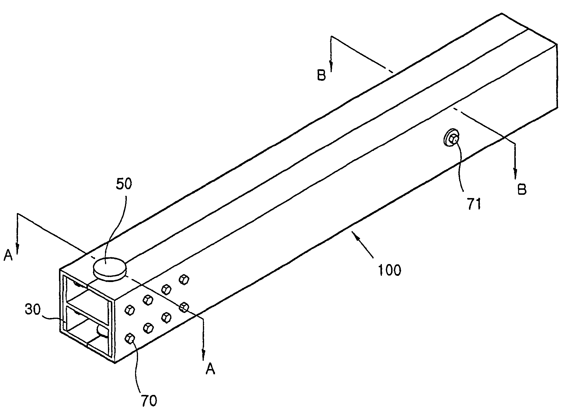
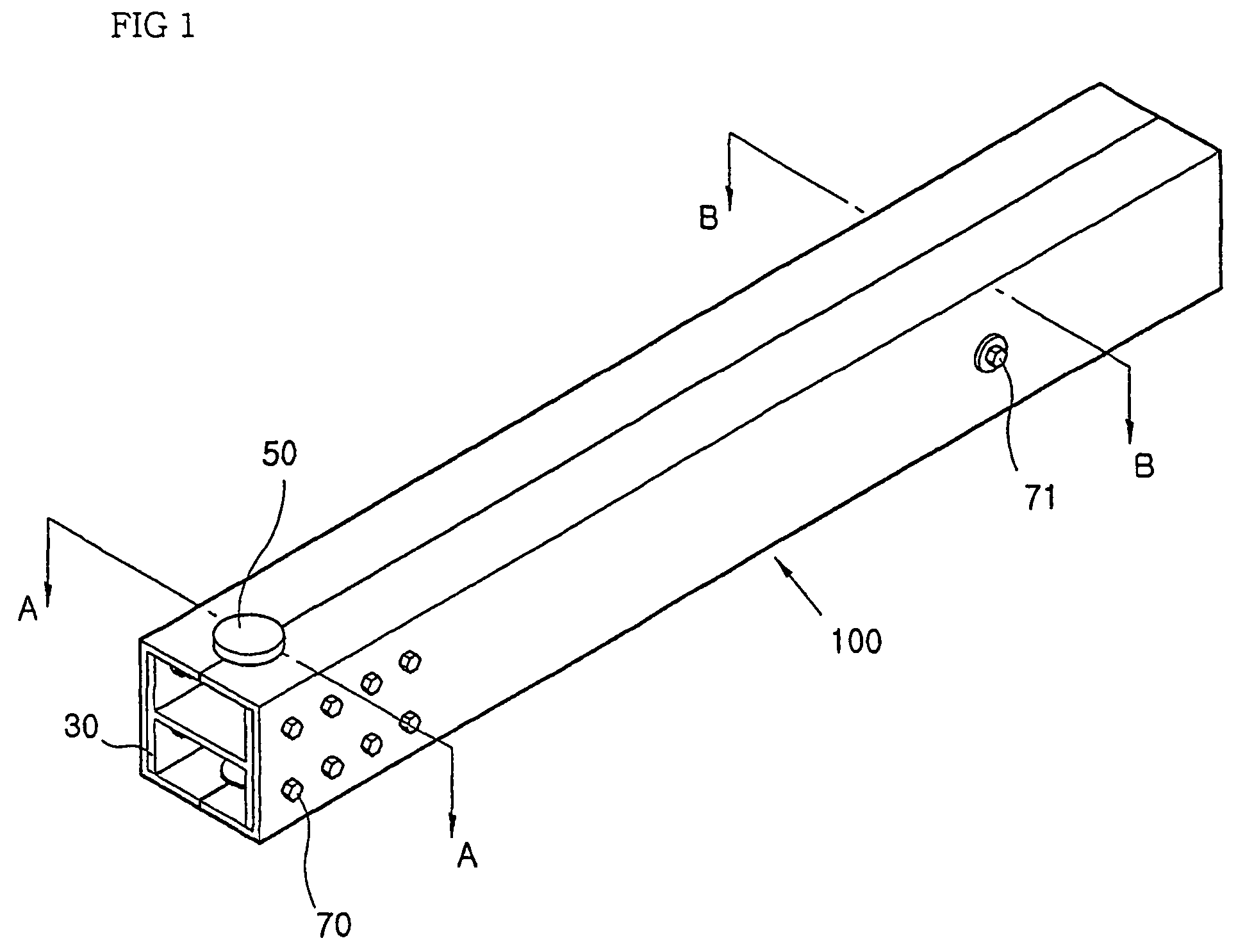
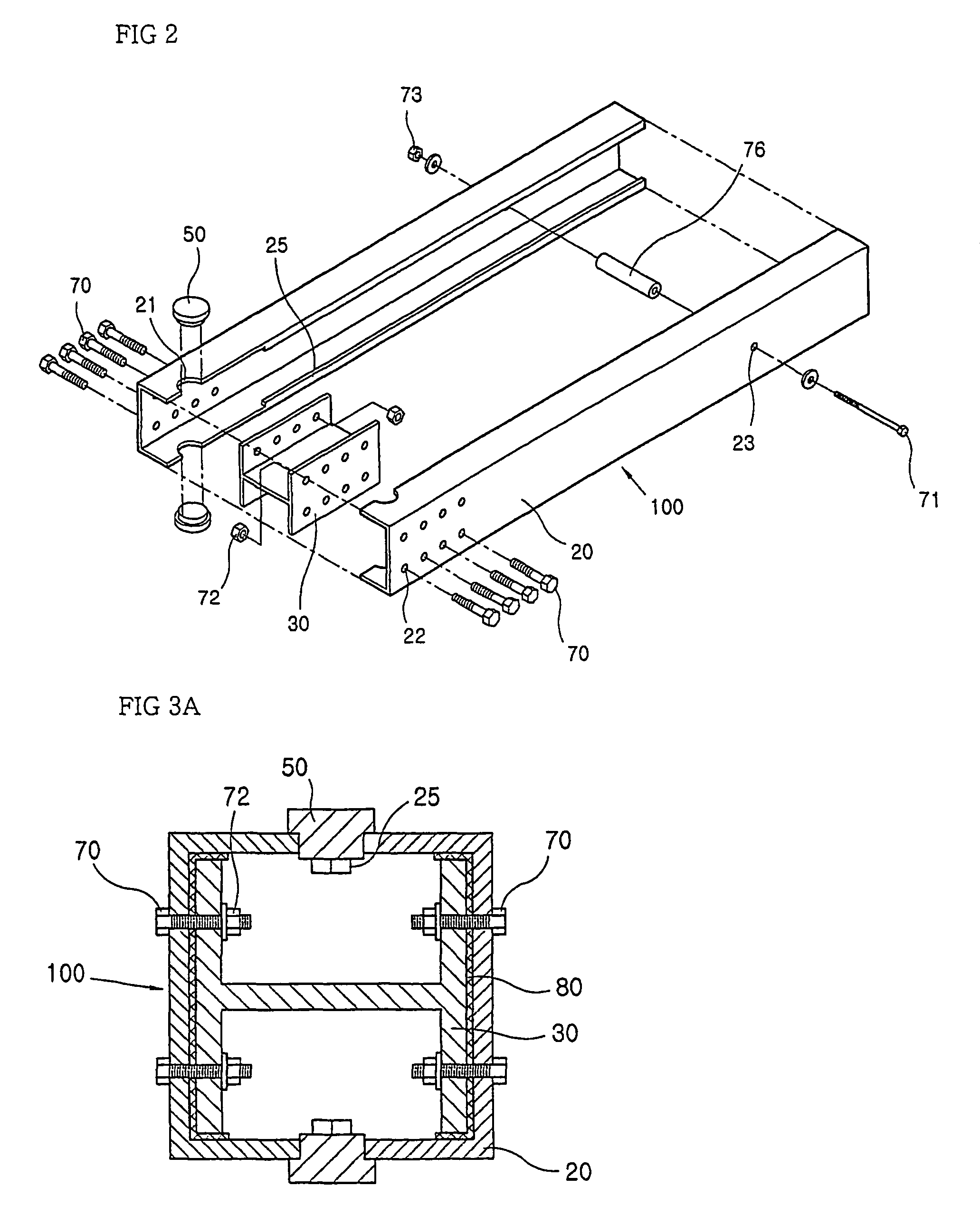
[0065]Referring to FIGS. 1 through 3B, a tubular structure according to the present invention is made of two channels, that is, first and second channels 20 each having a C-shaped section with inwardly bent lips or flanges, in which the first and second channels 20 are opposed to each other and assembled with each other. In each of the first and second channels 20, connection holes 22 are formed on the wide surfaces, flanges 25 which are bent inwards are formed at the edges of the opening sides on the narrow surfaces, and the flanges 25 are removed from the edges of the opening sides on the narrow surfaces only at the portions where the connection holes 22 are formed.

[0066]Also, the half a working access hole 21 is located on each of the narrow surfaces of the first and second channels 20. After assembly, a closure 50 is inserted in each of the working access holes 21.

[0067]Connection holes 23 are located at the intermediate portion on each of the wide surfaces in the tubular struct...

second embodiment

[0073]In the tubular structure according to the present invention as shown in FIGS. 5A and 5B, the channels each having the C-shaped section which are the first and second channels 20a each having the same section are aligned to face each other and assembled with each other. In each of the first and second channels 20a, the connection holes 22 are formed on the wide surface in which the narrow surface is formed inwards from the channel.

[0074]Also, the half a working access hole 21 is formed on each of the narrow surfaces of the first and second channels 20a. After assembly, a closure 50 is inserted therein and removed therefrom.

[0075]The connection holes 23 are located in the intermediate portions of the tubular structure and fitted with a long bolt 71 and are engaged with a nut 73, to thereby support the intermediate portions of the first and second channels 20a.

[0076]Like the first embodiment of the present invention, a spacer 76 mounted on a long bolt 71 is provided in the insid...

third embodiment

[0079]Referring to FIGS. 6A and 6B, channels 20b applied in the tubular structure according to the present invention each have an L-shaped cross-section and are opposed to each other and assembled with each other.

[0080]Since the working access holes 21, the connection holes 22 and 23, the closure 50 and the reinforcement unit in the third embodiment are provided like the first and second embodiments, the detailed description thereof will be omitted.

[0081]FIG. 7 is a perspective view showing part of the whole tubular structure illustrating examples of connection structures of the pillar and pillar and beam and beam according to the present invention.

[0082]Referring to FIG. 7, the lower portion of the pillar structure according to the present invention is a portion “A” which is vertically mounted on a concrete foundation 10. Also, the beam structure is a portion “B” which is extended from the lateral portion of the pillar structure. That is, the pillar structure is vertically fixed on...


PUM


Abstract

This invention relates to an elongated hollow non-deformable structure that can be used as beams and pillars of modular building structures. The structure includes first and second elongated C-shaped channels (20) with inwardly bent flanges (25) and means for holding the two channels (20) together so that the flanges (25) contact each other. The first and second C-shaped channels (20) may be formed without flanges (25). L-shaped (42) and T-shaped (40) and H-shaped flanges of appropriate design are provided with holes in the flanges at predetermined locations to correspond to the holes in the end portions of the beams and pillars. There are plugable holes (21) provided in the end portions of the beams and pillars so that workers can easily access inside the hollow space to use nuts (72), washers, and bolts (70) to couple the elongated hollow structures together. Instead of the C-shaped channel (20) structure two identical L-shaped channels (20b) may be used.

Description

FIELD OF THE INVENTION[0001]The present invention relates to a hollow tubular structure usable as a pillar or a beam in a building, and to a building assembly comprised of tubular pillar and beam structures assembled on a concrete foundation.BACKGROUND OF THE INVENTION[0002]In the case of a current architectural structure constructed using pillar and beam structures, a light-weight frame member can be used to make the pillars. The resulting architectural structure has an increased space, an excellent heat isolation ability and a strong moisture-prevention capability, to thus provide a comfortable housing environment. However, the manufacturing of the existing pillar and beam structures is a complicated construction process. That is, the manufacturing of the pillars and beams from respective connection portions requires a welding of the portions together, which impedes an efficient assembly. Also, it is not easy to maintain heat isolation at the beam and pillar connection sections. A...

Claims


Application Information

Patent Timeline
IPC IPC(8): E04C3/30E04B1/24E04C3/04E04C3/06E04C3/32
CPCE04B1/24E04C3/06E04C3/32E04C2003/0465E04B2001/2415E04B2001/2418E04B2001/2451E04B2001/2457E04B2001/2463E04B2001/2472E04C2003/0413E04C2003/043E04C2003/0439E04C2003/0452E04B2001/2406
Inventor LEE, DAE-JUN
Owner LEE DAE JUN
Why Eureka
Try Eureka