Cam drive gear and valve operating system drive gear for engine

a technology of cam drive and operating system, which is applied in the direction of valve drive, valve details, valve arrangement, etc., can solve the problems of cam chain chattering at its portions wrapped around the sprockets, increase in engine size, etc., and achieve the effect of effectively restrainting the cam chain, enhancing mountability, and reducing the number of components

Active Publication Date: 2007-01-02
HONDA MOTOR CO LTD
View PDF12 Cites 10 Cited by
  • Summary
  • Abstract
  • Description
  • Claims
  • Application Information

AI Technical Summary

Benefits of technology

[0007]A cam drive gear for an engine is described where the distance between the axes of a crankshaft and an idle shaft bearing an idle gear thereon can be made smaller, thereby contributing to a reduction in the size of the engine.
[0008]In addition, a valve-operating system drive gear for an engine is also described where it is possible to restrain a cam chain from chattering at its portion wrapped around a drive sprocket.

Problems solved by technology

In the cam drive gear disclosed in Japanese Patent No. 3309700, the primary drive gear with the comparatively large diameter is meshed with the idle gear, so that it is necessary for the distance between the axes of the crankshaft and the idle shaft rotatably supporting the idle gear to be set comparatively large, leading to an increase in the size of the engine.
However, the cam chain may chatter at its portions wrapped around the sprockets due to, for example, elongation of the cam chain or wear of the cam chain or of the drive sprocket and the driven sprocket.

Method used


Image

  • Cam drive gear and valve operating system drive gear for engine
  • Cam drive gear and valve operating system drive gear for engine
  • Cam drive gear and valve operating system drive gear for engine

Examples


Embodiment Construction

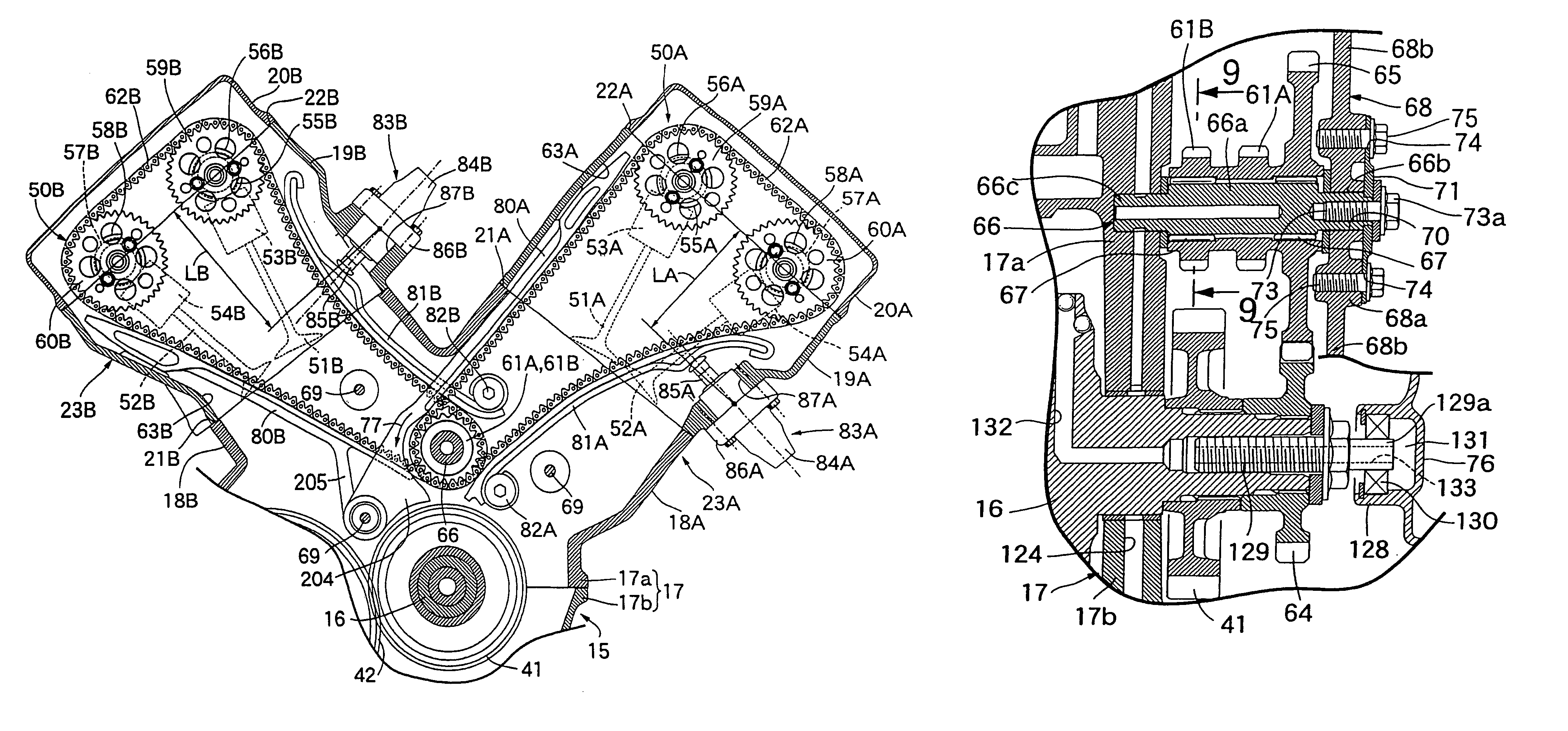
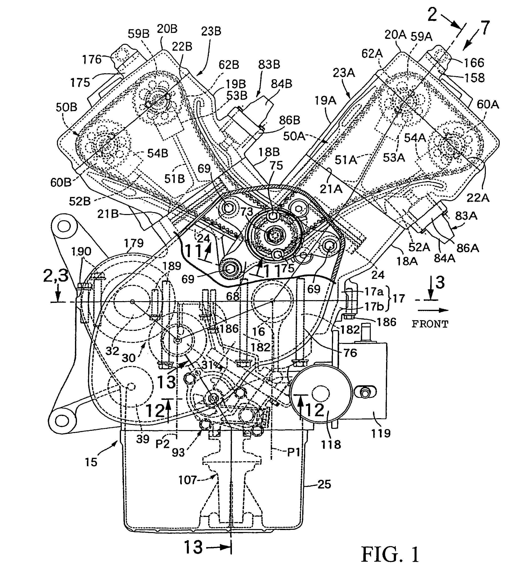
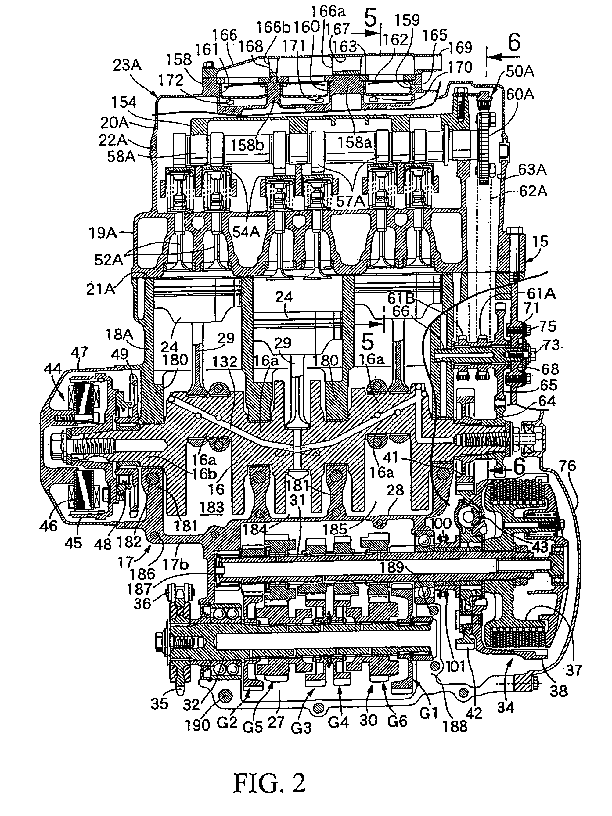
[0038]In FIG. 1, a five-cylinder V-type engine, for example, is shown mounted on a vehicle or a motorcycle. An engine main body 15 of the engine includes a crankcase 17 rotatably bearing a crankshaft 16 having an axis extending in the left-right direction of the motorcycle, a first cylinder block 18A connected to the crankcase 17 on the front side along the running direction of the motorcycle, a first cylinder head 19A connected to a top connection surface 21A of the first cylinder block 18A, a first head cover 20A connected to a top connection surface 22A of the first cylinder head 19A, a second cylinder block 18B connected to the crankcase 17 on the rear side along the running direction of the motorcycle, a second cylinder head 19b connected to a top connection surface 21B of the second cylinder block 18B, and a second head cover 20B connected to a top connection surface 22B of the second cylinder head 19B.

[0039]The crankcase 17 includes an upper case 17a and a lower case 17b conn...


PUM


Abstract

A cam drive gear for an engine is described where the distance between the axes of a crankshaft and an idle shaft bearing an idle gear thereon can be made smaller, thereby contributing to a reduction in the size of the engine. In addition, a valve-operating system drive gear for an engine is also described where it is possible to restrain a cam chain from chattering at its portion wrapped around a drive sprocket.

Description

[0001]This application claims priority under 35 U.S.C. § 119 to Japanese Patent Application Nos. 2004-380363 and 2005-022109, filed on Dec. 28, 2004 and Jan. 28, 2005 respectively.FIELD[0002]The present invention relates to a drive gear for an engine, for example a cam drive gear and a valve-operating system drive gear.BACKGROUND[0003]A cam drive gear for an engine is disclosed in Japanese Patent No. 3309700 in which a primary drive gear provided on a crankshaft is meshed with an idle gear rotatably borne on an idle shaft provided on an engine main body while having an axis parallel to the crankshaft, and drive sprockets are rotated together with the idle gear.[0004]The primary drive gear provided on the crankshaft is formed with a comparatively large diameter so as to transmit rotational torque of the engine to the transmission side. In the cam drive gear disclosed in Japanese Patent No. 3309700, the primary drive gear with the comparatively large diameter is meshed with the idle g...

Claims


Application Information

Patent Timeline
Patent Type & Authority Patents(United States)
IPC IPC(8): F01L1/02
CPCF01L1/02F01L1/022F02B61/02F02B75/22F01L2001/0537
Inventor OSHITA, TORUKISAICHI, TORUNAKAYAMA, SHINGOSAWA, ATSUSHITSUBOTA, RYUSHI
Owner HONDA MOTOR CO LTD
Why Eureka
Try Eureka