Recirculating fan thermostat

a technology of recirculating fan and thermostat, which is applied in the direction of ventilation system, heating type, domestic cooling apparatus, etc., can solve the problems of wasting energy, affecting the efficiency of the home air conditioner,

Inactive Publication Date: 2007-01-02
BRAEBURN SYST
View PDF7 Cites 53 Cited by
  • Summary
  • Abstract
  • Description
  • Claims
  • Application Information

AI Technical Summary

Benefits of technology

[0008]In accordance with the present invention, a programmable thermostat is provided with a heat-cool switch, a temperature values input, and a fan switch with on, auto, and recirculating positions, and a microprocessor that superimposes a fan recirculating mode or cycle on the heat-cool or off modes or cycles by determining when the heat-co

Problems solved by technology

During periods when a heating or cooling system is not running, the air in a home becomes stagnant.
T

Method used


Image

  • Recirculating fan thermostat
  • Recirculating fan thermostat
  • Recirculating fan thermostat

Examples


Embodiment Construction

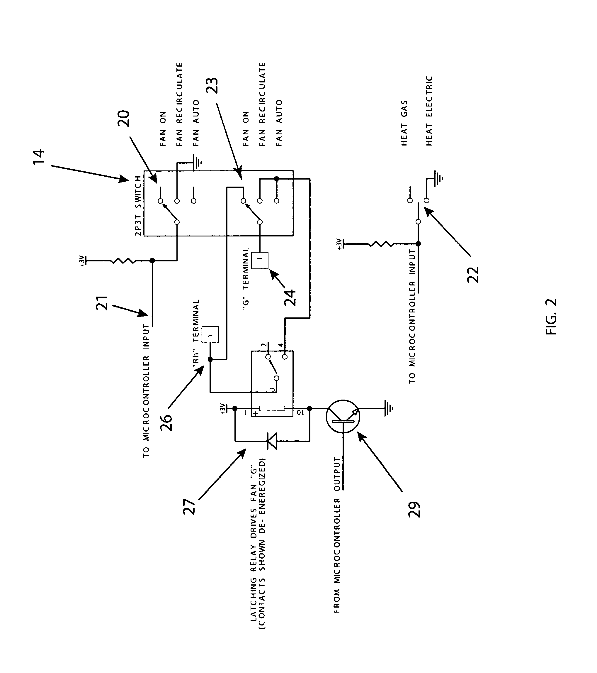
[0017]Referring to the drawings and particularly FIG. 3, a programmable electronic thermostat 10 is illustrated including a housing 11, an LCD display 12, temperature control switches 13, programming switches 15, a system-cool-off heat switch 16, a time switch 17, and an auto-recirculate-on switch 14 for the fan. The fan switch 14 is also illustrated in FIG. 2 and is seen to be a 2P, 3T switch with poles 20 providing an output to the input 21 of the microprocessor to tell the microprocessor what the state of the fan switch 14 is. A gas-electric switch 22 shown at the bottom of FIG. 2, provides an input to the microprocessor so that the furnace logic and not the thermostat controls the fan operation during the gas heating cycle. In the fan “on” position illustrated, pole 23 connects fan terminal 24 to 24-volt power from RH terminal 26. In the fan auto and recirculate positions, fan operation is controlled by a latching relay 27 shown with its contacts in the deenergized position in F...


PUM


Abstract

A programmable thermostat with a heat-cool switch, a temperature value input, and a fan switch with on, auto, and recirculating positions, and a microprocessor that superimposes a fan recirculating mode or cycle on the heat-cool or off modes or cycles by determining when the heat-cool or off cycles have been off for a user selectable time period; 2 hours, for example, and if so initiating a fan cycle for a predetermined time; 12 minutes for example, to provide a more uniform room temperature by mixing hotter and cooler air and cleaner air by running more space air through the heating and cooling system filter assembly.

Description

BACKGROUND OF THE INVENTION[0001]Programmable thermostats have gained wide popularity in the last decade because of microprocessor cost reduction, the ease of programming these small microprocessors, and the cost savings and comfort enhancement of programmed temperature adjustments with parameters such as time of day, outside temperature, season of year, and other parameters. Such low cost microprocessors have the capability of functions in excess of those currently being utilized and provide an opportunity for enhanced heating-cooling and fan control not currently utilized at a small incremental cost.[0002]The present invention deals with the circulation of air within the building and particularly the mixing of hot and cold air within the space and the environmental cleanliness of the air. In moderate outside temperatures, in the range of 35 to 80 degrees, the off cycles in both the heating and cooling modes will increase over the bordering colder or hotter ranges. This long off cy...

Claims


Application Information

Patent Timeline
IPC IPC(8): F24F7/00F25D17/00G05D23/32
CPCG05D23/1904F24F11/0012F24F11/30F24F2110/10F24F11/52F24F11/65F24F11/61F24F11/74
Inventor MOORE, GLENN A.
Owner BRAEBURN SYST
Why Eureka
Try Eureka