Mold for forming a contact lens and method of preventing formation of small strands of contact lens material during contact lens manufacture

a technology of contact lens and mold, which is applied in the direction of dough shaping, manufacturing tools, instruments, etc., can solve the problems of contact lens being rejected, excess reactive mixture overflowing the cavity, and large formation of reactive mixture thin pieces, so as to reduce the amount of surface area

Inactive Publication Date: 2007-01-02
JOHNSON & JOHNSON VISION CARE INC
View PDF125 Cites 19 Cited by
  • Summary
  • Abstract
  • Description
  • Claims
  • Application Information

AI Technical Summary

Benefits of technology

[0007]This invention provides a mold for forming a contact lens comprising an overflow collector. The overflow collector is a volume preferably at least partly defined by a structure which causes the overflow reactive mixture to be accumulated, and not to spread out as it would upon the typically flat surface of a prior art mold. The overflow collector also reduces the amount of the surface area of the overflow that contacts the ambient or inert environment, preferably the overflow collector reduces the surface area of the overflow that contacts the ambient or inert environment by more than twenty-five percent as compared to a mold having a flat overflow area, more preferably by more than fifty percent as compared to a mold having a flat overflow area. The overflow collector assists in the removal of the overflow reactive mixture from the contact lens manufacturing process. The overflow collector preferably prevents t

Problems solved by technology

The placement of the second mold portion onto the first mold portion typically causes excess reactive mixture to overflow the cavitycontacting one or both mold portions.
During the hydration and washing step(s), any residual reactive monomer overflow, which if present is usually a thin or small piece which broke off from the bigger piece (which adhered to the second mold portion) washes off the first mold portion flange and may attach itself to a contact lens, which may later cause the contact lens to be rejected.
The reactive mixture which forms the contact lens within the mold is not effecte

Method used


Image

  • Mold for forming a contact lens and method of preventing formation of small strands of contact lens material during contact lens manufacture
  • Mold for forming a contact lens and method of preventing formation of small strands of contact lens material during contact lens manufacture
  • Mold for forming a contact lens and method of preventing formation of small strands of contact lens material during contact lens manufacture

Examples


Embodiment Construction

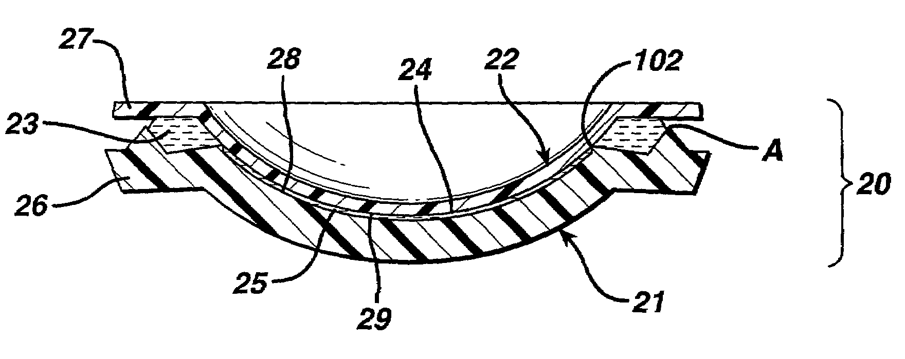
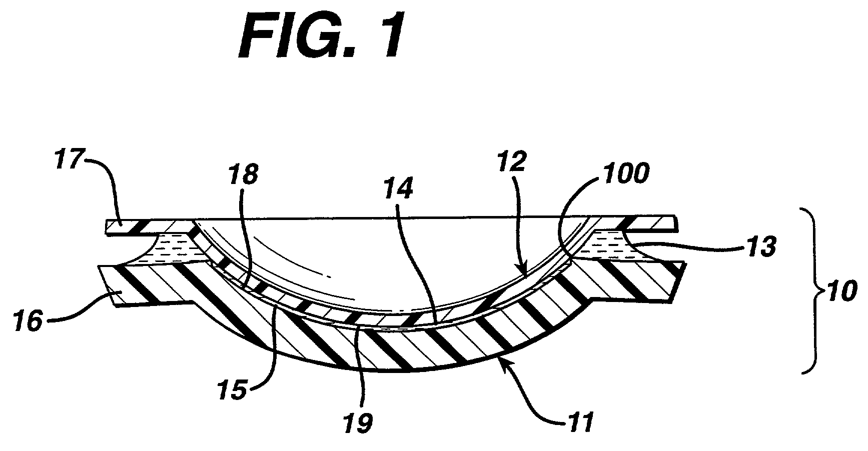
[0016]FIG. 1 shows a cross-section of a prior art contact lens mold 10 which consists of a first mold portion 11, and a second mold portion 12. The mold 10 is shown assembled and dosed with a reactive mixture 15. Molds like the one shown and their use for molding contact lenses have been fully described in for example, U.S. Pat. Nos. 5,238,388; 5,326,505 and 5,540,410; incorporated herein by reference. Typically the mold portions comprise polystyrene, polypropylene, polyethylene or the like; however, more durable materials such as quartz or glass can be used to make the molds of this invention.

[0017]The first mold portion 11 and the second mold portion 12 define a cavity 14 within which a reactive mixture 15, e.g. reactive monomers or uncrosslinked polymers, react to form a contact lens. The reactive mixture 15 typically comprises a hydrogel forming composition, for example, it may comprise hydroxyethyl methacrylamide and / or other monomers, and crosslinkers, and / or other composition...


PUM

PropertyMeasurementUnit
Lengthaaaaaaaaaa
Lengthaaaaaaaaaa
Lengthaaaaaaaaaa

Abstract

This invention provides a mold for forming a contact lens comprising an overflow collector, which causes the overflow reactive mixture to be accumulated, and not to spread out as it would upon the typically flat surface of a prior art mold. This invention further provides a method of preventing the formation of contaminating pieces of overflow reactive mixture comprising the step of: preventing the overflow reactive mixture from spreading out on the mold.

Description

CROSS-REFERENCE TO RELATED APPLICATIONS[0001]This is a continuation of application Ser. No. 09 / 476,273, filed on Jan. 3, 2000, now U.S. Pat. No. 6,368,522.FIELD OF THE INVENTION[0002]This invention relates to a mold used for forming a contact lens and for a method of preventing the formation of small strands of contact lens material from the overflow of the contact lens mold during contact lens manufacture.BACKGROUND OF THE INVENTION[0003]One way to manufacture soft contact lenses is to mold contact lenses in plastic molds. Typically there are two mold portions which when assembled form a cavity between the mold portions. A reactive mixture which reacts within the cavity forms a contact lens. Typically a first mold portion is dosed with the reactive mixture, and the second mold portion is placed on the first mold portion, and then the reactive mixture is reacted. The placement of the second mold portion onto the first mold portion typically causes excess reactive mixture to overflow...

Claims


Application Information

Patent Timeline
IPC IPC(8): B29D11/00G02C7/04B29C33/00B29C39/02B29C39/24B29C39/26B29L11/00
CPCB29C33/0055B29D11/00057Y10S425/808B29D11/00586B29D11/00
Inventor ANSELL, SCOTT FREDERICKWINDEY, JAN ALBERT MARIAFOLEY, JR., KENNETH W.KREBSBACH, GERALD ROBERTSMITH, ROBERT MACDONALDCROWE, JR., CARL G.
Owner JOHNSON & JOHNSON VISION CARE INC
Why Eureka
Try Eureka