Connector for corrugated coaxial cable and method

a technology connector, which is applied in the direction of coupling device connection, coupling device details, securing/insulating coupling contact members, etc., can solve the problems of weak physical connection between the connector and the cable, breakage of electrical connections, and difficulty in attaching a conventional coaxial connector to the end of corrugated coaxial cable. , to achieve the effect of reliable electrical connection, reduced volume of the chamber, and large surface area electrical connection

Inactive Publication Date: 2007-01-02
JOHN MEZZALINGUA ASSOC INC
View PDF33 Cites 195 Cited by
  • Summary
  • Abstract
  • Description
  • Claims
  • Application Information

AI Technical Summary

Benefits of technology

[0012]After the cable has been inserted into the connector, the cover is forced axially toward the body to reduce the volume of the chamber, compress the elastomer, flow the elastomer radially inwardly and force the conductive member against the outer conductor to establish a reliable, large surface area electrical connection with the outer surface of the corrugated cable. The conductive member is electrically connected to the connector body so that a reliable connection is established between the outer conductor and the connector body. The contact pin engages the central conductor. The cover is frictionally held on the body so that the compressed elastomer is confined and resiliently holds the conductive member against the outer cable conductor.
[0013]Mounting of the connector on the cable forms reliable electrical connections with the inner and outer cable conductors and a strong physical connection between the connector and the cable. The physical connection extends along an appreciable length of the cable. The elastomer is deformed radially inwardly to hold the conductive member against the outer conductor at a number of corrugations in order to form a strong interlocking physical connection between the connector and cable. The connection is stronger than the physical connection formed between a corrugated coaxial cable and a conventional connector.

Problems solved by technology

It is difficult and time consuming to attach a conventional coaxial connector to the end of corrugated coaxial cable.
The physical connection between the connector and cable is not strong and may fail and break the electrical connections.
Mounting of conventional corrugated cable connectors in the field is difficult, particularly when preformed in the weather many feet above the ground on the top of a transmission tower.
If the connector is not mounted correctly on the end of the cable, the connection will fail.
Delayed failure requires connector replacement, frequently at the top of the tower and greatly increases overall cost of the installation.

Method used


Image

  • Connector for corrugated coaxial cable and method
  • Connector for corrugated coaxial cable and method
  • Connector for corrugated coaxial cable and method

Examples


Embodiment Construction

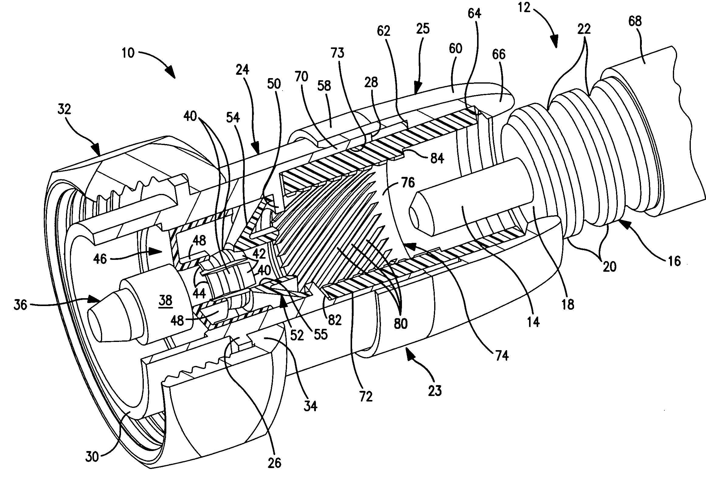
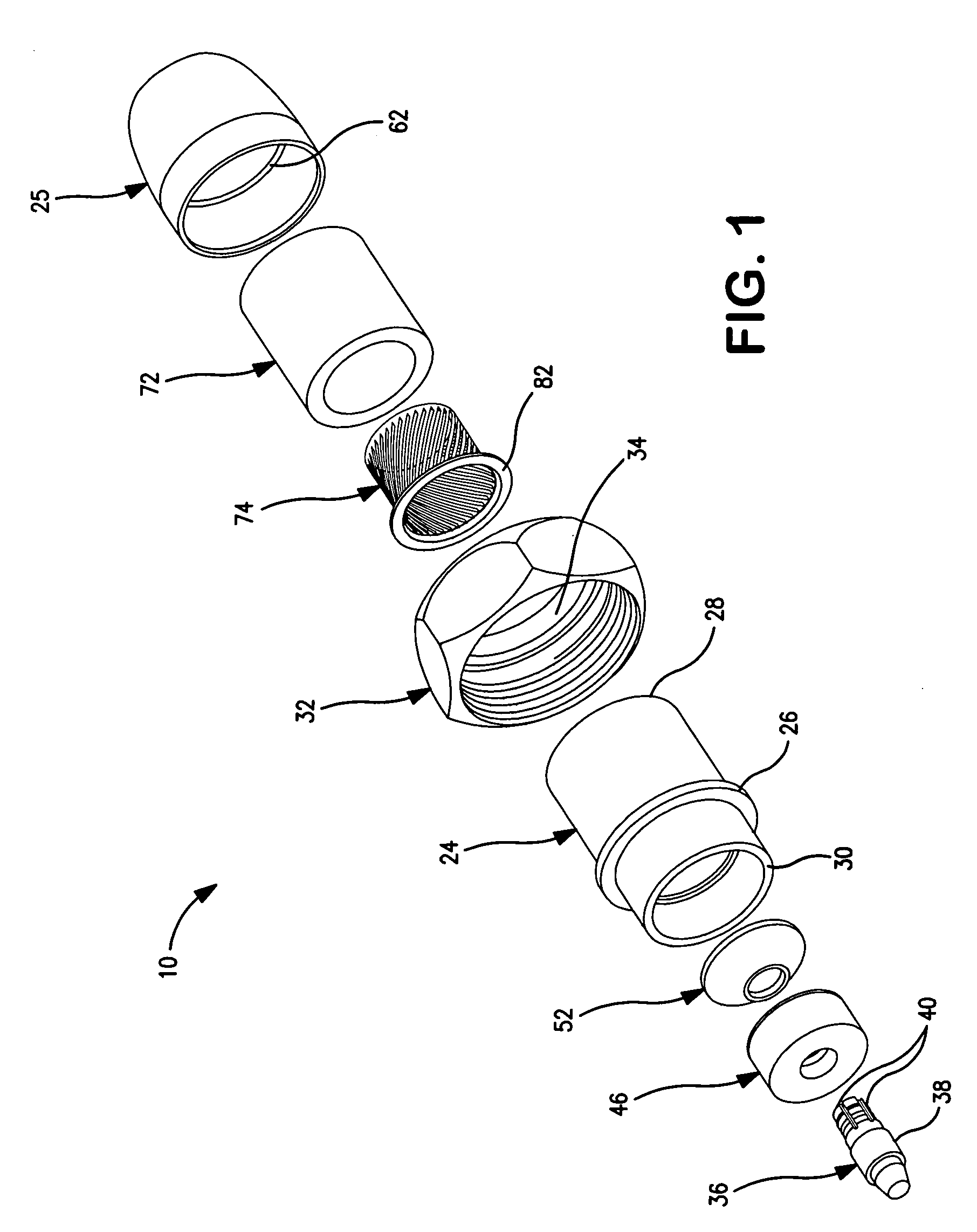
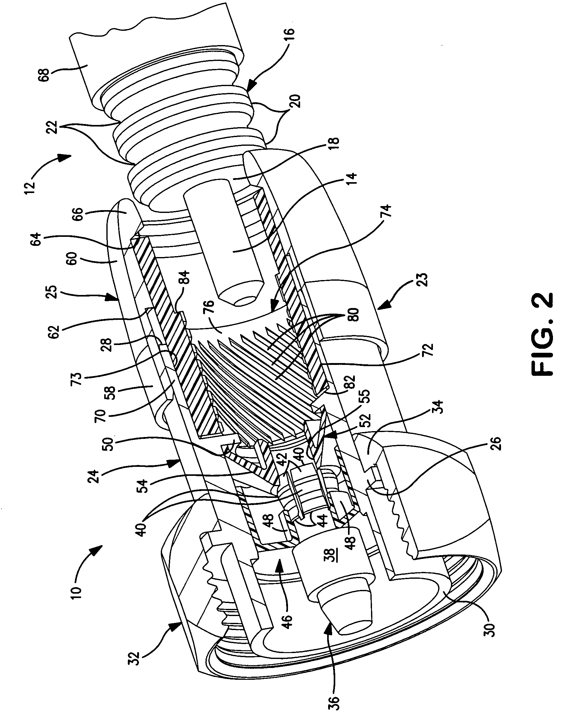
[0023]Coaxial cable connector 10 is mounted on the end of corrugated coaxial cable 12 and forms electrical connections with the inner metal conductor 14 and outer corrugated metal conductor 16 in the cable. The inner and outer cable conductors are separated by foamed insulation 18. The connector 10 establishes electrical connections between the cable conductors and a cable mounting port. As shown in FIG. 2, the corrugated outer conductor 16 includes a number of circular peaks 20 and valleys 22 spaced axially along the length of the cable. Alternatively, the outer conductor may be spiral wound with spiral peaks and valleys extended along the length of the cable.

[0024]Coaxial cable connector 10 includes a two-part tubular metal body 23 formed from body members 24 and 25. Member 24 has an outer flange 26 extending around the body between the cable end 28 and port end 30 of the member. Threaded coupler nut 32 is fitted over end 28 and includes a radially inward collar 34 engaging flange...


PUM


Abstract

An electrical connector is mounted on a corrugated coaxial cable. An electrical connection with the outer conductor of the cable is formed by compressing an elastomer body surrounding the end of the cable and flowing the body inwardly against the cable to hold a conductive member in electrical connection with the outer conductor.

Description

FIELD OF THE INVENTION[0001]The invention relates to connectors for mounting on the ends of corrugated coaxial cables to establish electrical connections with the inner and outer conductors in the cables, and to methods for mounting connectors on the ends of corrugated coaxial cables.BACKGROUND OF THE INVENTION[0002]Corrugated coaxial cable is commonly used to carry high frequency electrical signals. In the wireless and cellular telephone industries corrugated cable is used to transmit power signals from amplifiers to antennas on the tops of towers and for radio transmitter applications. The cable is typically about ⅜″ to 2″ in diameter and includes a metal central conductor surrounded by a corrugated metal outer conductor. Foam insulation fills the space between the conductors. The corrugated outer conductor improves cable flexibility.[0003]A corrugated coaxial cable may have an outer conductor that has a series of circular peaks and valleys spaced along the length of the cable. Al...

Claims


Application Information

Patent Timeline
Patent Type & Authority Patents(United States)
IPC IPC(8): H01R9/05
CPCH01R9/05H01R24/564H01R2103/00H01R13/5205
Inventor MONTENA, NOAH P.
Owner JOHN MEZZALINGUA ASSOC INC
Why Eureka
Try Eureka