Tool change system for a machine

a technology for changing machines and tools, applied in the direction of manufacturing tools, instruments, transportation and packaging, etc., can solve the problems of inadmissible explosion hazards, mechanical damage and failure of coating units, etc., and achieve the effect of reliably preventing the danger of unintentional opening of the tool change device of the machin

Inactive Publication Date: 2007-01-02
DURR SYST INC
View PDF59 Cites 10 Cited by
  • Summary
  • Abstract
  • Description
  • Claims
  • Application Information

AI Technical Summary

Benefits of technology

[0003]The task of the invention is a tool change system in which the hazard of uni

Problems solved by technology

This air supply by the robot itself can lead to unintentional release of the atomizer possibly during the coating operation during improper control, which not only results in mec

Method used


Image

  • Tool change system for a machine
  • Tool change system for a machine

Examples


Embodiment Construction

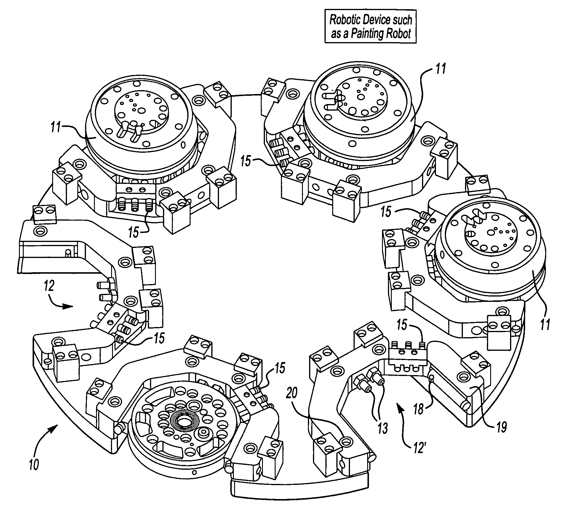
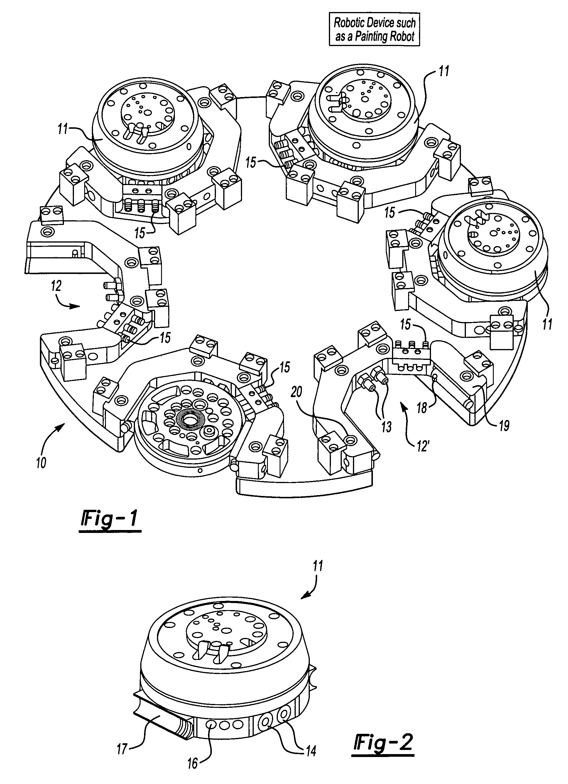
[0010]Referring to FIG. 1, a mounting plate 10 defines a periphery and has six storage places 12 for the changeable (not shown) atomizer and / or other tools, like hood openers, measurement devices, and the like (not shown). Each atomizer and / or tool includes a flange part 11 releasable from a fixed part of a machine, for example, a painting robot, shown schematically in FIG. 1, that is secured during operation to the fixed part of the robot by a pneumatic cylinder closure. The mounting plate 10 is a carousel-like station rotatable relative to the painting robot. Alternatively, the mounting plate 10 is linearly movable (not shown) relative the painting robot.

[0011]The storage places 12 are formed by fork-like recesses into which the flange part11 of the tools separable by the robot can be introduced in the direction of arrow 12′. A tool holder 19 mounted to float in all three spatial axes preferably has media connections defined by at least two connections 13 for air, rinsing agents a...


PUM


Abstract

A plurality of atomizers or other tools are disposed in a mounting plate (10) in storage places (12), respectively. The mounting plate (10) is rotatable relative a paint robot of a coating installation and has a pneumatic lock or a tool holder (19) that can only be released automatically during storage of the atomizers by an external control device of the mounting plate.

Description

FIELD OF THE INVENTION[0001]The invention concerns a tool change system for a machine with an automatically (multiaxis) moveable tool according to the preamble of the independent claim. In particular, a robot can be involved and its tool can be an atomizer for series coating of workpieces, like vehicle bodies.BACKGROUND OF THE INVENTION[0002]Tool change systems for painting robots, whose atomizer is fastened to a flange that forms the releaseable part, which is secured by pneumatic forces on a machine flange forming the fixed part, are state of the art. To release the atomizer, an air connection is operated by the robot itself for opening of a closure cylinder of the atomizer change device of the robot. This air supply by the robot itself can lead to unintentional release of the atomizer possibly during the coating operation during improper control, which not only results in mechanical damage and failure of the coating unit, but also results in an inadmissible hazard of explosion by...

Claims


Application Information

Patent Timeline
IPC IPC(8): B23Q3/155B05B13/04B23Q1/00B25J15/04
CPCB05B13/0431B23Q1/0018B23Q3/15526B25J15/0491B05B12/1454Y10S483/901Y10T483/17Y10T483/134Y10T483/13Y10T483/11Y10T483/1809Y10T483/1882Y10T483/15
Inventor NOLTE, HANS J.MELCHER, RAINERBAUMANN, MICHAELGIULIANO, STEFANO
Owner DURR SYST INC
Why Eureka
Try Eureka