Spring system for re-centering a movable object

a technology of re-centering and movable objects, which is applied in the direction of mechanical control devices, manual control with multiple controlled members, and single control member, etc., can solve problems such as interference with the precision of users, and achieve the effect of preventing oscillation

Inactive Publication Date: 2007-01-02
AVAGO TECH WIRELESS IP SINGAPORE PTE
View PDF12 Cites 28 Cited by
  • Summary
  • Abstract
  • Description
  • Claims
  • Application Information

AI Technical Summary

Benefits of technology

[0005]The present invention includes a moveable puck that moves within a puck field of motion. The puck field of motion is defined by a boundary. Arcuate springs connect the puck to the boundary. Each arcuate spring has a first end connected to the puck and a second end connected to the boundary, and applies a force to the puck that maintains the puck in a predetermined region of the puck field of motion when no external force is applied to the puck. Each arcuate spring includes a planar spiral member in one embodiment. In another embodiment, one of the arcuate springs also applies a force that dampens any oscillations in the puck position when the puck returns to the predetermined region in the puck field of motion. In another embodiment, the puck also includes an electrode that is electrically connected to a point outside the puck field of motion by one of the arcuate springs. In another embodiment, the boundary is defined by an opening in a layer of material. In another embodiment, the puck and the springs are constructed from a portion of the layer of material.

Problems solved by technology

In addition, the force the user applies to move the puck should not vary over the puck field of motion, since such variations can interfere with the precision with which the user can position the puck.

Method used


Image

  • Spring system for re-centering a movable object
  • Spring system for re-centering a movable object
  • Spring system for re-centering a movable object

Examples


Embodiment Construction

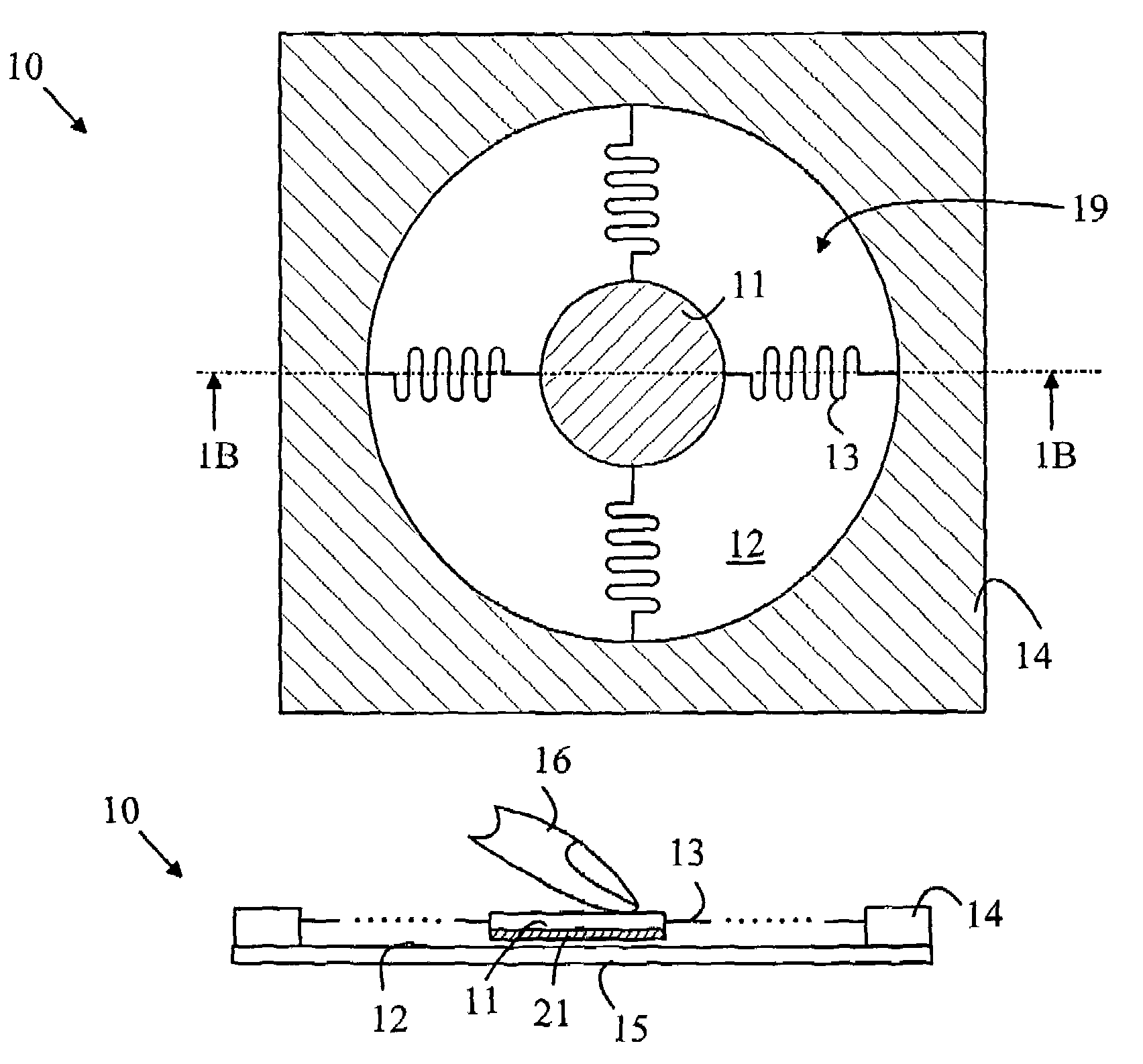
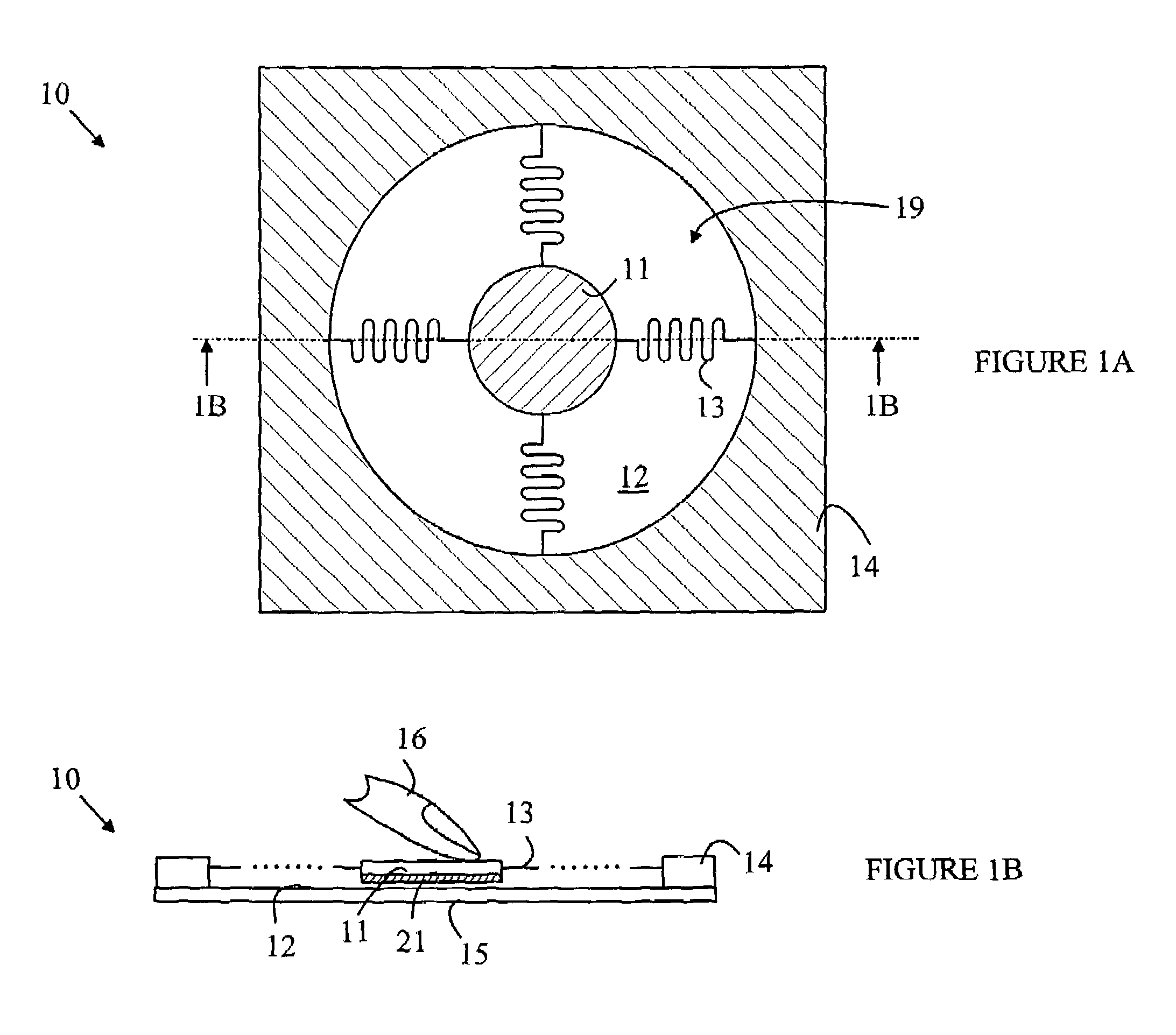
[0010]The manner in which the present invention provides its advantages can be more easily understood with reference to FIGS. 1A–1B, which illustrate a pointing device 10 that utilizes a puck of the type discussed above to implement a pointing device. FIG. 1A is a top view of pointing device 10 and FIG. 1B is a cross-sectional view of pointing device 10 through line 1B—1B shown in FIG. 1A. Pointing device 10 includes a puck 11 that moves over a surface 12 of a substrate 15 within a puck field of motion 19 in response to a lateral force being applied to puck 11. The force is typically applied to puck 11 by a user's finger, thumb or multiple fingers. In addition, pointing device 10 includes a sensing mechanism for determining the position of puck 11 on surface 12. When the user releases puck 11, the meander springs shown at 13 that connect puck 11 to the periphery 14 of the puck field of motion return the puck to a predetermined location in the puck field of motion.

[0011]The position ...


PUM


Abstract

A puck is movable within a puck field of motion defined by a boundary. Arcuate springs connect the puck to the boundary. Each arcuate spring has a first end connected to the puck and a second end connected to the boundary, and applies a force to the puck that maintains the puck in a predetermined region of the puck field of motion when no external force is applied to the puck. In an embodiment, each arcuate spring includes a planar spiral member. The arcuate springs can also apply a force that dampens any oscillations in the puck position when the puck returns to the predetermined region in the puck field of motion. The puck can also include an electrode that is electrically connected to a point outside the puck field of motion by one of the arcuate springs.

Description

FIELD OF THE INVENTION [0001]The present invention relates to mechanisms for re-centering a movable object within a two-dimensional field of motion when no external force is applied to the object.BACKGROUND OF THE INVENTION [0002]Consider an apparatus in which an object moves over a two-dimensional surface within a predetermined area in response to an external force applied to the object. The object will be referred to as a puck in the following discussion, and the area over which it is permitted to move will be referred to as the puck field of motion. For example, a computer pointing device that is analogous to a “mouse” is described in a co-pending patent application. This device includes a puck that moves over a surface within a puck field of motion in response to a user applying force to the puck via a finger. The surface has position sensors that sense the position of the puck within the puck field of motion and report that position to a data processing system coupled to the de...

Claims


Application Information

Patent Timeline
Patent Type & Authority Patents(United States)
IPC IPC(8): G09G5/00G06F3/033
CPCG06F3/03548G06F3/0338G05G2009/04714G06F3/0354
Inventor HARLEY, JONAHHOEN, STORRS
Owner AVAGO TECH WIRELESS IP SINGAPORE PTE
Why Eureka
Try Eureka