Data pulse spectrum control

Active Publication Date: 2007-01-02
MICROSOFT TECH LICENSING LLC
View PDF8 Cites 11 Cited by
  • Summary
  • Abstract
  • Description
  • Claims
  • Application Information

AI Technical Summary

Benefits of technology

[0006]The present invention provides methods and apparatus that reduce adjacent channel interference for a wireless peripheral device. In an embodiment of the invention, a direct digital synthesizer generates a waveform having intermediate angular changes during a transition time between symbol intervals. After the transition time, the direct digital synthesizer generates the waveform with an angular value that corresponds to the symbol being transmitted. Analysis of different configurations of the embodiment indicates that adjacent channel power (ACP) may be reduced by adjusting design parameters, including the transition time and a number of intermediate angular changes that are inserted during the transition time. An embodiment of the invention may be applicable to wireless peripheral devices, including computer peripheral devices and wireless terminals (mobile terminals).
[0007]In an embodiment, apparatus and method provide a waveform that is characterized by one of two designated frequencies in response to a value of an input. The input is formatted as information bits, in which a symbol corresponds to an information bit. Other embodiments may associate a plurality of information bits to a symbol. The waveform is further characteriz

Problems solved by technology

With the proliferation of wireless computer peripherals, e.g. keyboards and mice, the possibility of interference of associated wireless communications from other wireless computer peripherals is increased.
If two wireless devices are in close proximity of each other while operating at adjacent wireless channels, adjacent channel interference may be induced.
If the level of interference is great enough (as may be gauged by a bit error rate), data communications between each wireless peripheral device to the associated computer may be degraded and even impaired.
Consequently, a user of the computer may experience input errors that may or may not be detected by software that executes on the computer and

Method used


Image

  • Data pulse spectrum control
  • Data pulse spectrum control
  • Data pulse spectrum control

Examples


Example

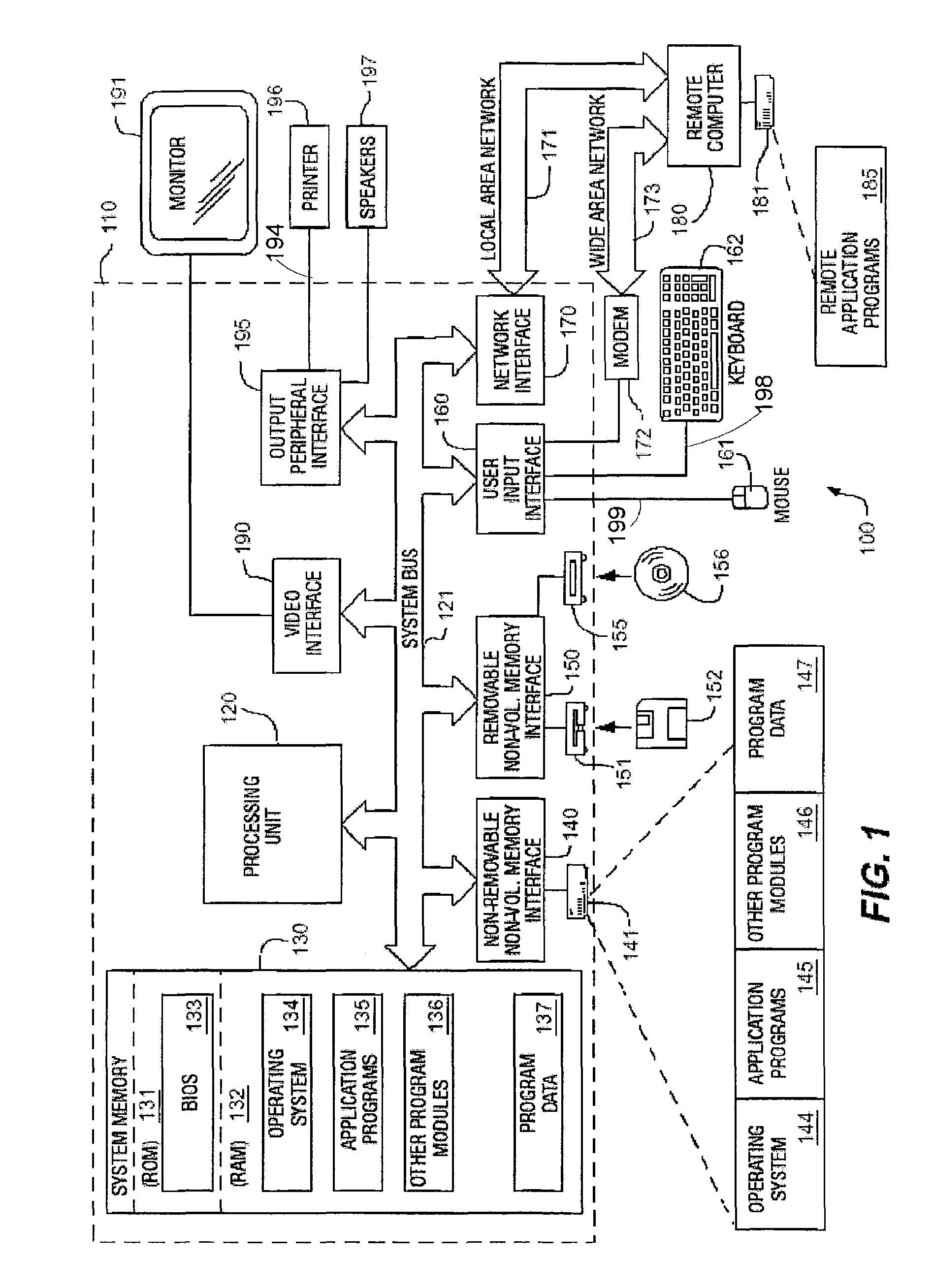
[0027]FIG. 1 illustrates an example of a suitable computing system environment 100 on which the invention may be implemented. In particular, FIG. 1 shows an operation of a wireless pointer device 161, e.g. an optical wireless mouse, in the context of computing system environment 100. The computing system environment 100 is only one example of a suitable computing environment and is not intended to suggest any limitation as to the scope of use or functionality of the invention. Neither should the computing environment 100 be interpreted as having any dependency or requirement relating to any one or combination of components illustrated in the exemplary operating environment 100.

[0028]The invention is operational with numerous other general purpose or special purpose computing system environments or configurations. Examples of well known computing systems, environments, and / or configurations that may be suitable for use with the invention include, but are not limited to, personal comp...


PUM


Abstract

The present invention reduces adjacent channel interference for a wireless peripheral device. A direct digital synthesizer generates a waveform having intermediate angular changes during a transition time between symbol intervals. After the transition time, the direct digital synthesizer generates the waveform with an angular value that corresponds to the symbol being transmitted. In an exemplary embodiment, a generated waveform is characterized by one of two designated frequencies in response to a value of an input information bit. The waveform is further characterized by at least one intermediate frequency during a transition time between a change of the designated frequency. Another embodiment of the invention utilizes phase changes rather than frequency changes during reduce adjacent channel interference. With another aspect of the invention, methods are provided to determine waveform parameters for reducing adjacent channel power (ACP) to a maximum level of interference.

Description

FIELD OF THE INVENTION[0001]The present invention relates to controlling adjacent channel interference between wireless peripheral devices.BACKGROUND OF THE INVENTION[0002]With the proliferation of wireless computer peripherals, e.g. keyboards and mice, the possibility of interference of associated wireless communications from other wireless computer peripherals is increased. Typically, a wireless computer peripheral is assigned a wireless channel from a set of wireless channels, in which the wireless computer peripheral transmits to an associated computer through a corresponding interface circuit that is configured with the computer. As an example, a wireless keyboard that is associated with a personal computer (PC) may be assigned a 50 KHz radio frequency (RF) channel centered around 27.145 MHz, while a wireless mouse may be assigned another 50 KHz RF channel centered around 27.195 MHz. Because the transmitted signal on the wireless channel is time-limited, with each information b...

Claims


Application Information

Patent Timeline
IPC IPC(8): H04B15/00
CPCH04B1/109H04L25/03834H04W28/04H04B2001/1045
Inventor ALBULET, MIHAI
Owner MICROSOFT TECH LICENSING LLC
Why Eureka
Try Eureka