Transmission of point-to-multipoint services to a destination area

a point-to-multipoint service and destination area technology, applied in the field of areal point-to-multipoint services, can solve the problems of inability to efficiently map logical names, and achieve the effects of reducing load, facilitating logical names determination, and ensuring service quality

Inactive Publication Date: 2007-01-02
NOKIA TECHNOLOGLES OY
View PDF7 Cites 21 Cited by
  • Summary
  • Abstract
  • Description
  • Claims
  • Application Information

AI Technical Summary

Benefits of technology

[0012]The invention is based on the idea that at the service centre that receives the service request the geographical area indicated by the logical name is linked to other service centres and / or to network nodes of the receiving service centre and to cells located within the area of the network nodes. The service is transmitted to the cells in a conventional manner through the network nodes, whereas a service request is forwarded to other service centres. The invention thus provides the advantage that logical names can be efficiently and reliably mapped to distribution addresses of the service. A further advantage the invention provides is that logical names are very easy to determine, and one and the same destination area can have various different logical names. Another advantage is that with a single service request the service requester can cover a wide area. The area does not need to be limited in any way according to network borders, network node service areas or other predetermined areas of the network, such as location areas; Furthermore, the network operator can add a new service centre to the network and divide the service area of a former service centre into service areas of the former and the new service centre in such a way that from the service requester's point of view the network functions as if the service areas had not been divided at all.
[0013]In a preferred embodiment of the invention the service request is transmitted unchanged to other service centres. This provides the advantage that the system does not need different service request messages according to who is the sender of the service request, or whether the service centre receiving the service request is located in the same network or in a different network; one and the same service request is always valid.
[0015]In another preferred embodiment of the invention the service centre replaces the destination area of the service request with a destination area of the second service centre before the service request is transmitted to the destination area. This simplifies the determining of logical names in different networks and provides a means for preventing the service request to be transferred back and forth between the service centres.
[0016]In another preferred embodiment of the invention the service areas of the service centres overlap at least to some extent, the common area then belonging only to the service area of the service centre with a smaller load. This provides the advantage that the operator can secure an equal quality of service irrespective of the load of the first service centre that receives the service request.

Problems solved by technology

A problem with the above described system is that it fails to determine how to map efficiently logical names in order to one or more network element addresses allowing the service to be transmitted to an entire geographical destination area that may cover a plurality of service areas of different packet radio networks or PTM service centres.

Method used


Image

  • Transmission of point-to-multipoint services to a destination area
  • Transmission of point-to-multipoint services to a destination area
  • Transmission of point-to-multipoint services to a destination area

Examples


Embodiment Construction

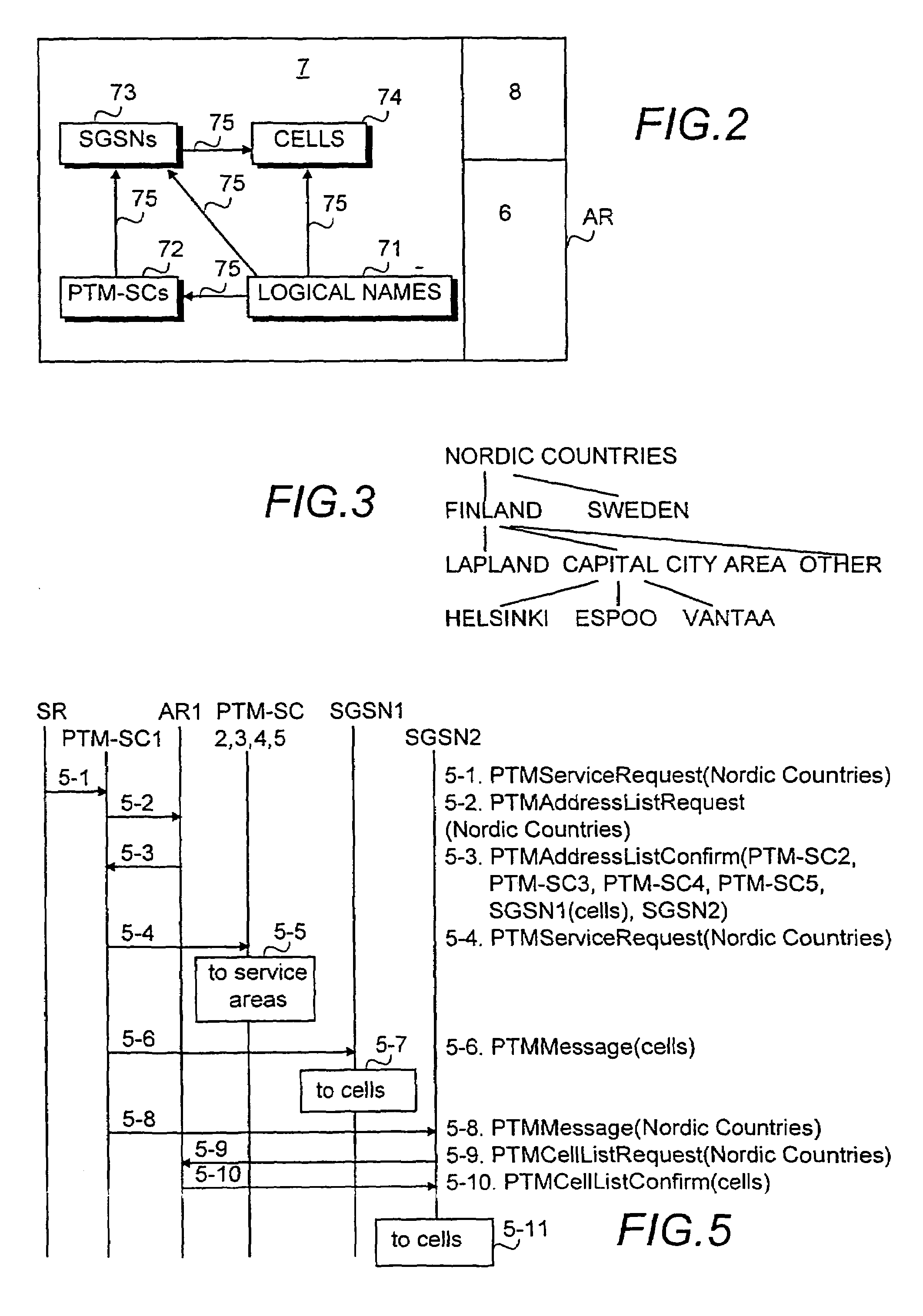
[0025]In the following the preferred embodiments of the invention will be described with reference to GPRS packet radio networks without, however, restricting the invention to any specific packet radio system. It is to be noted that a packet radio network only provides a physical connection between a PTM service centre and a service receiver, therefore its detailed operation and structure are not essential to the invention. Specifications for mobile communication systems in general and for the GPRS system in particular develop rapidly. The location of different functionalities in the network elements may change. Therefore all words and expressions used should be interpreted in their broadest sense; they are used to describe and not to limit the invention.

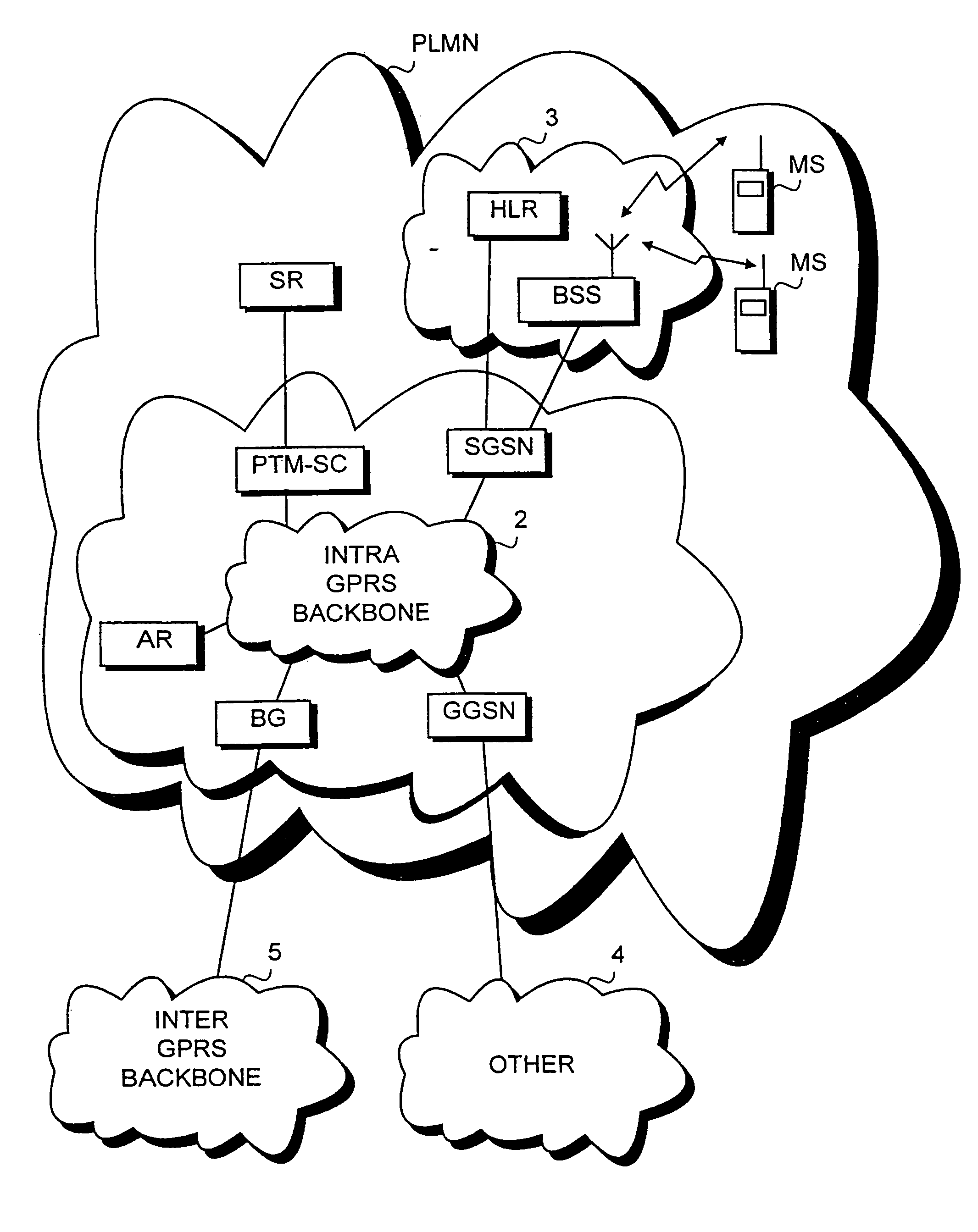
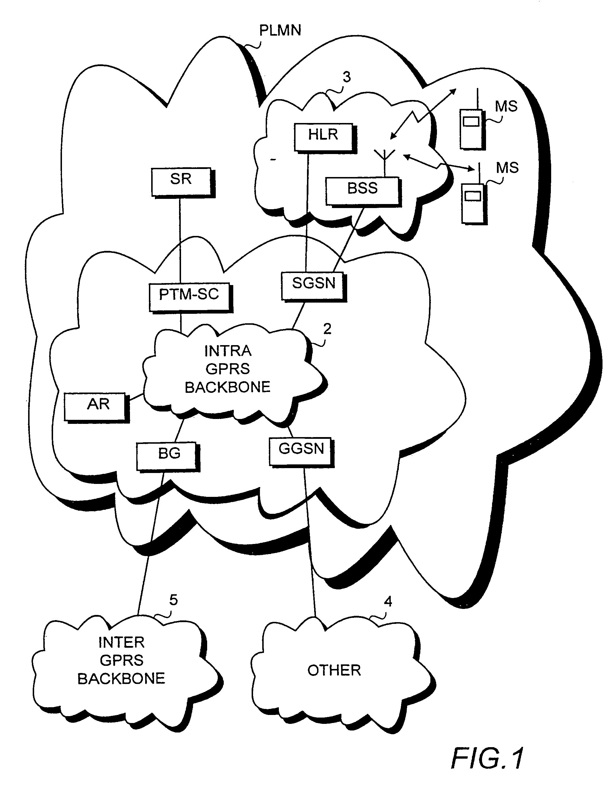
[0026]FIG. 1 shows one example of a GPRS packet radio network PLMN. A GPRS operational environment 1 comprises one or more subnetwork service areas interconnected by an Intra-PLMN GPRS Backbone Network 2. A subnetwork comprises a nu...


PUM


Abstract

A system, methods, an area register and a service center for transmitting point-to-multipoint services to a geographical destination area that can be indicated by using a logical name. Logical names must be mapped to distribution addresses. The system therefor comprises memory means (AR) for mapping each predetermined logical name (71) to one or more network element addresses (72,73) of the system. In addition, the system comprises one or more service centers which are arranged to inquire, in response to a received service request, the memory means (AR) for the addresses (72, 73) of the network elements corresponding to the logical name (71) of the destination area and to transmit the point-to-multipoint service to the geographical destination area via the network elements. The service is transmitted to cells in conventional manner via network nodes, while a service request is transmitted to other service centers.

Description

[0001]This application is a continuation of international application serial number PCT / FI99 / 00250, filed 26 Mar. 1999.BACKGROUND OF THE INVENTION[0002]The invention relates to areal point-to-multipoint services in a mobile communication system and particularly to mapping of a logical name of a geographical destination area of a service to network element addresses in order to allow one and the same service request to be used for reaching service areas of even a plurality of service centres controlling point-to-multipoint services.[0003]Mobile communication systems have been developed in an answer to a need to reach people when they are not at a fixed telephone terminal. With the increased use of various data transmission services in offices, different data services have been also introduced into mobile communication systems. Mobile communication networks, in turn, provide the user with an efficient access network to the actual data networks for mobile data transmission. For this pu...

Claims


Application Information

Patent Timeline
Patent Type & Authority Patents(United States)
IPC IPC(8): H04B15/00H04W4/06H04W8/26
CPCH04L12/189H04W4/06H04W8/26
Inventor MUHONEN, AHTI
Owner NOKIA TECHNOLOGLES OY
Why Eureka
Try Eureka