Low torque inner gimbal heat remover

Inactive Publication Date: 2007-01-09
LOCKHEED MARTIN CORP
View PDF11 Cites 7 Cited by
  • Summary
  • Abstract
  • Description
  • Claims
  • Application Information

AI Technical Summary

Benefits of technology

[0014]A primary advantage of the present invention is that it provides an efficient, lightweight, cost effective, less complex, and highly reliable solution to directly eliminate unwanted heat without causing severe torque disturbances to the inner gimbal assembly.
[0015]Other objects, advantages and novel features, and further scope of applicability of the present invention will be set forth in part in the detailed description to follow, taken in conjunction with the accompanying drawings, and in part will become apparent to those skilled in the art upon examination of the following, or may be learned by practice of the invention. The objects and advantages of the invention may be realized and attained by means of the instrumentalities and combinations particularly pointed out in the appended claims.
[00

Problems solved by technology

Some sensor gimbals, however, contain heat-generating devices, and current gimbal sensor designs are unable to efficiently remove heat generated from major sensor components.
Sensor payloads generate substantial amounts of internal heat that must be removed; most known assemblies remove heat using liquid cooling, conduction, and air-to-air heat exchanger cooling systems, which are expensive, heavy and consume valuable payload space.
Thus the cooling methods typically employed are not practical, especially with two rela

Method used


Image

  • Low torque inner gimbal heat remover
  • Low torque inner gimbal heat remover
  • Low torque inner gimbal heat remover

Examples


Embodiment Construction

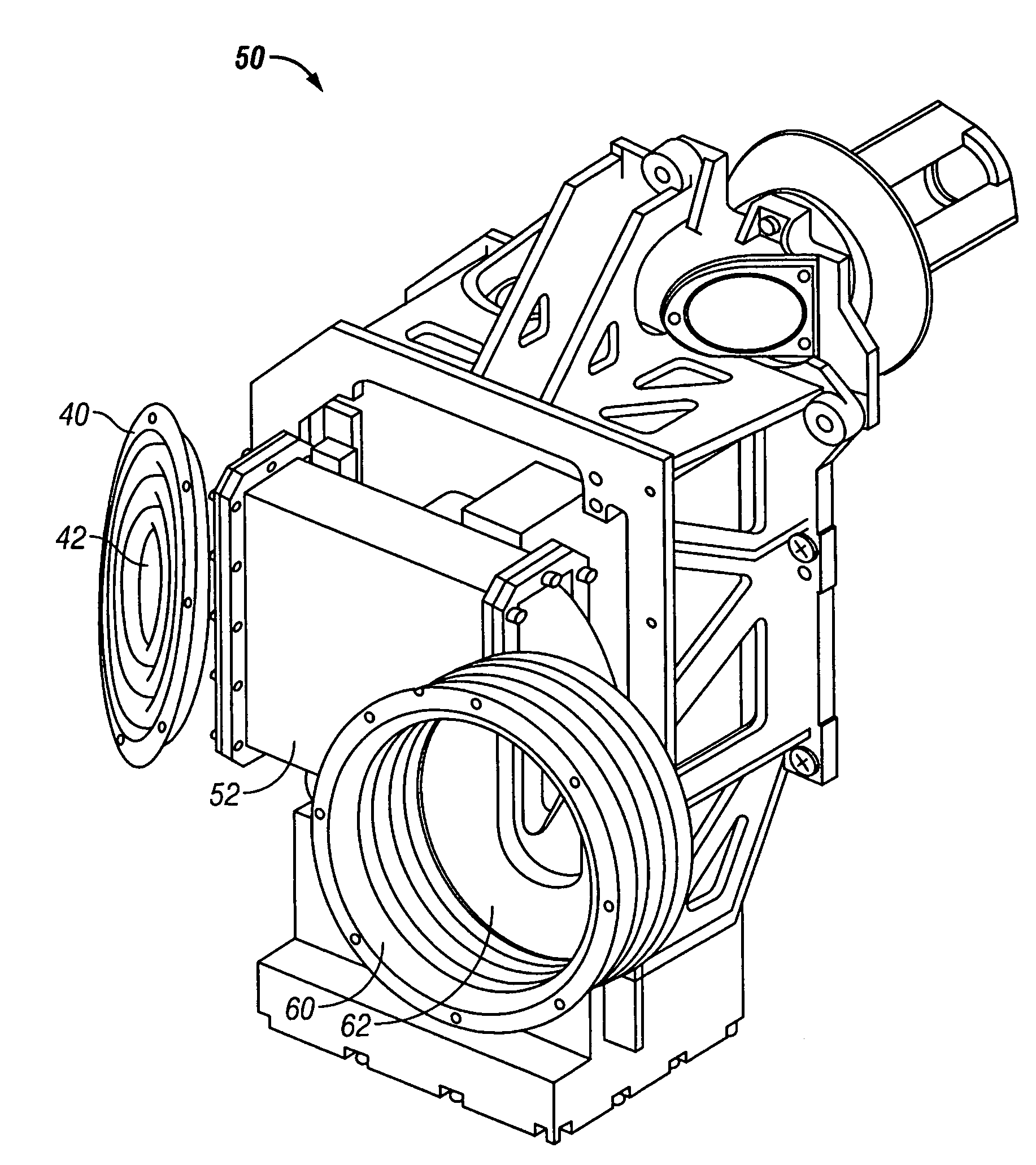
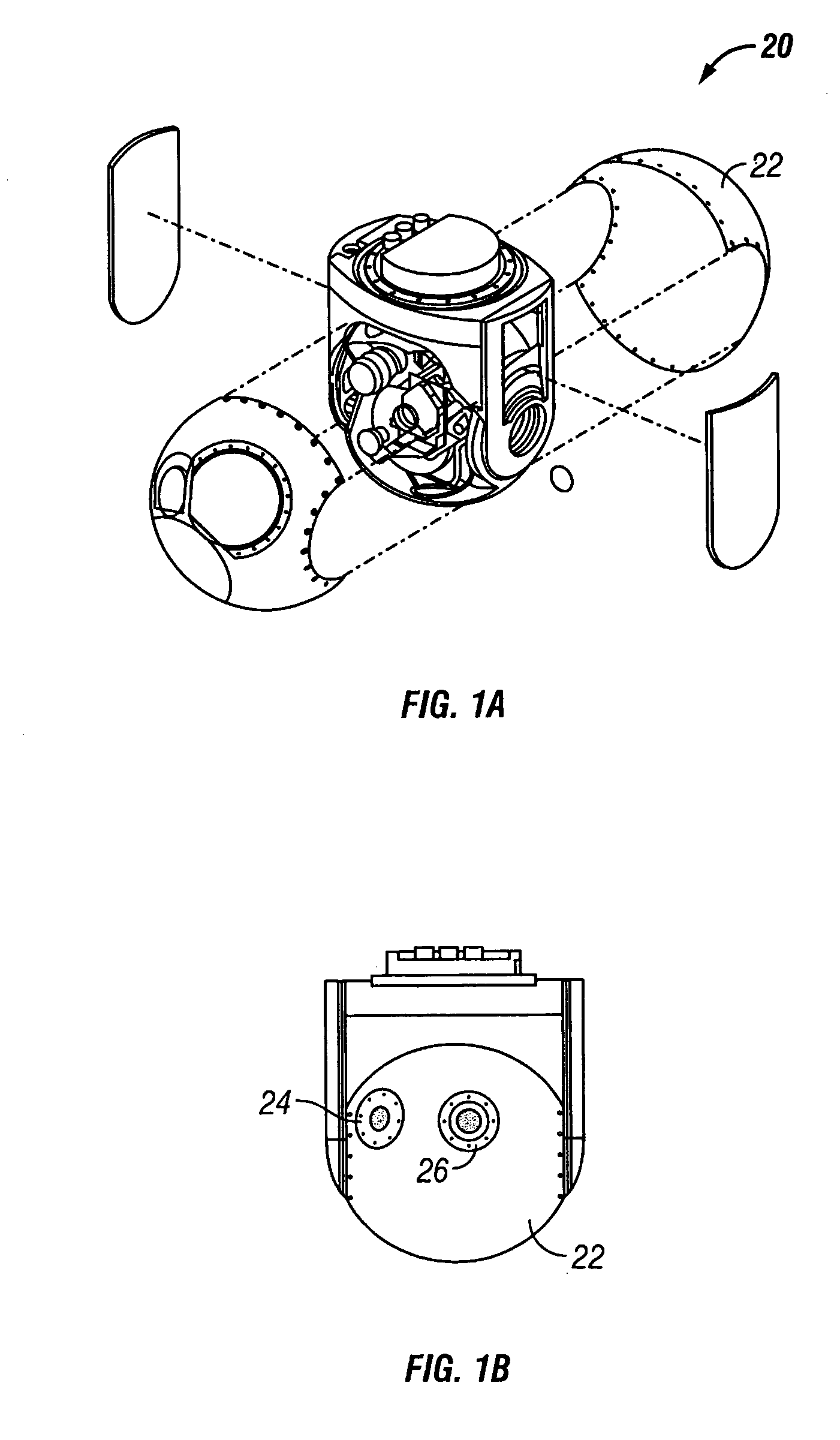
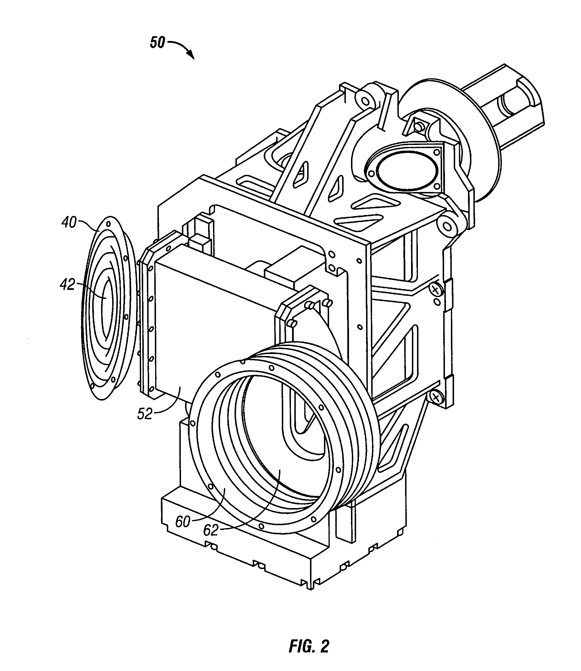
[0024]The invention is a bellows apparatus for removing heat build-up in a gimbal device mounting heat-generating devices. The apparatus comprises an inlet bellows and an exhaust bellows. The bellows are free flexing and provide for very low torque to gimbal devices, which must have unimpeded gimbaled movement. Each bellows functions as an air duct and has a plurality of raised circumferential convolutes formed in the surface. One opening of the inlet bellows is attached to the outer shroud of the outer gimbal device, and the opening at the other end is attached to the heat source of the inner gimbal device. The exhaust bellows is likewise attached. An air movement means, such as a fan, preferably is disposed at the exit of the exhaust bellows to draw heated air away from the heat source to the environment outside the outer gimbal device. As air is drawn away from the heat source, cooler outside air is drawn through the inlet bellows to displace the heated air.

[0025]Turning now to t...


PUM


Abstract

A cooling assembly for removing heat form an enclosed environment containing a gimbal device. The assembly comprises an exhaust bellows equipped with a device to draw heated air from the heat source to the outer environment an inlet bellows through which cool, outside air enters to displace the heated air.

Description

BACKGROUND OF THE INVENTION[0001]1. Field of the Invention (Technical Field)[0002]The present invention relates to methods and apparatuses for cooling an enclosed gimbal device.[0003]2. Description of Related Art[0004]Note that the following discussion refers to a number of publications by author(s) and year of publication, and that due to recent publication dates certain publications are not to be considered as prior art vis-a-vis the present invention. Discussion of such publications herein is given for more complete background and is not to be construed as an admission that such publications are prior art for patentability determination purposes.[0005]Gimbal assemblies typically comprise a 3-axis assembly disposed within an outer 2-axis assembly to provide an overall 5-axis rotation. Such gimbal assemblies are commonly used to mount various technical devices, such as sensors, that must have freedom of movement in three dimensions. Some sensor gimbals, however, contain heat-genera...

Claims


Application Information

Patent Timeline
IPC IPC(8): F28F7/00F28F9/26F28F13/12
CPCF16M11/123F42B15/01F41G3/22
Inventor GO, GEORGEMYERS, JAMES R.
Owner LOCKHEED MARTIN CORP
Why Eureka
Try Eureka