
Tractor with reversible operator position for operation and transport

a technology of operator position and tractor, which is applied in the direction of steering control, loading-carrying vehicle superstructure, steering control of vehicle, etc., can solve the problems of limiting the transport speed of these windrowers and the inability to increase the transport speed of traveling in the engine forward direction, so as to achieve maximum safety and functionality

Active Publication Date: 2007-01-09
MACDON INDS
View PDF9 Cites 66 Cited by
  • Summary
  • Abstract
  • Description
  • Claims
  • Application Information

AI Technical Summary

Benefits of technology

The invention is a tractor with improved capabilities for transporting a header and other attachments. It includes a frame, engine, hydraulic pump, driven wheels, non-driven castor wheels, and a cab with a seat and control system. The tractor can rotate at higher speeds when the operator's seat is in the engine forward position, and the speed control allows for faster operation. The steering control and speed control can be adjusted based on the operator's position. The control system is responsive to movement of the operator's seat and can change the operation of various controls based on the position of the seat. The engine forward position allows for higher engine speed and the drive motor has a wider range of speed ranges for both high and low speeds. The control system includes switches on the operator's seat for controlling the speed and turn signals of the tractor. The header control includes a speed control for the header drive motor and a height control for the header to fall from a raised position to a cut height. The tractor can only be operated when the operator's seat is in the engine forward position.

Problems solved by technology

There has been a limit to the transport speed of these windrowers due to instability at high speed with the drive wheels ahead of the castor wheels (cab forward).
However, the purpose for traveling in the engine forward direction was not to be able to increase transport speed, as the machine traveled only 12 mph, the same as it would have in cab forward direction.

Method used


Image

  • Tractor with reversible operator position for operation and transport
  • Tractor with reversible operator position for operation and transport
  • Tractor with reversible operator position for operation and transport

Examples


Embodiment Construction

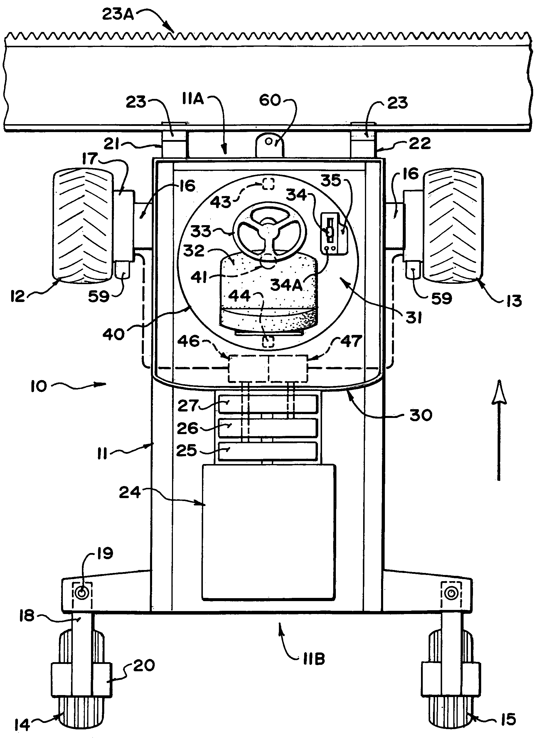
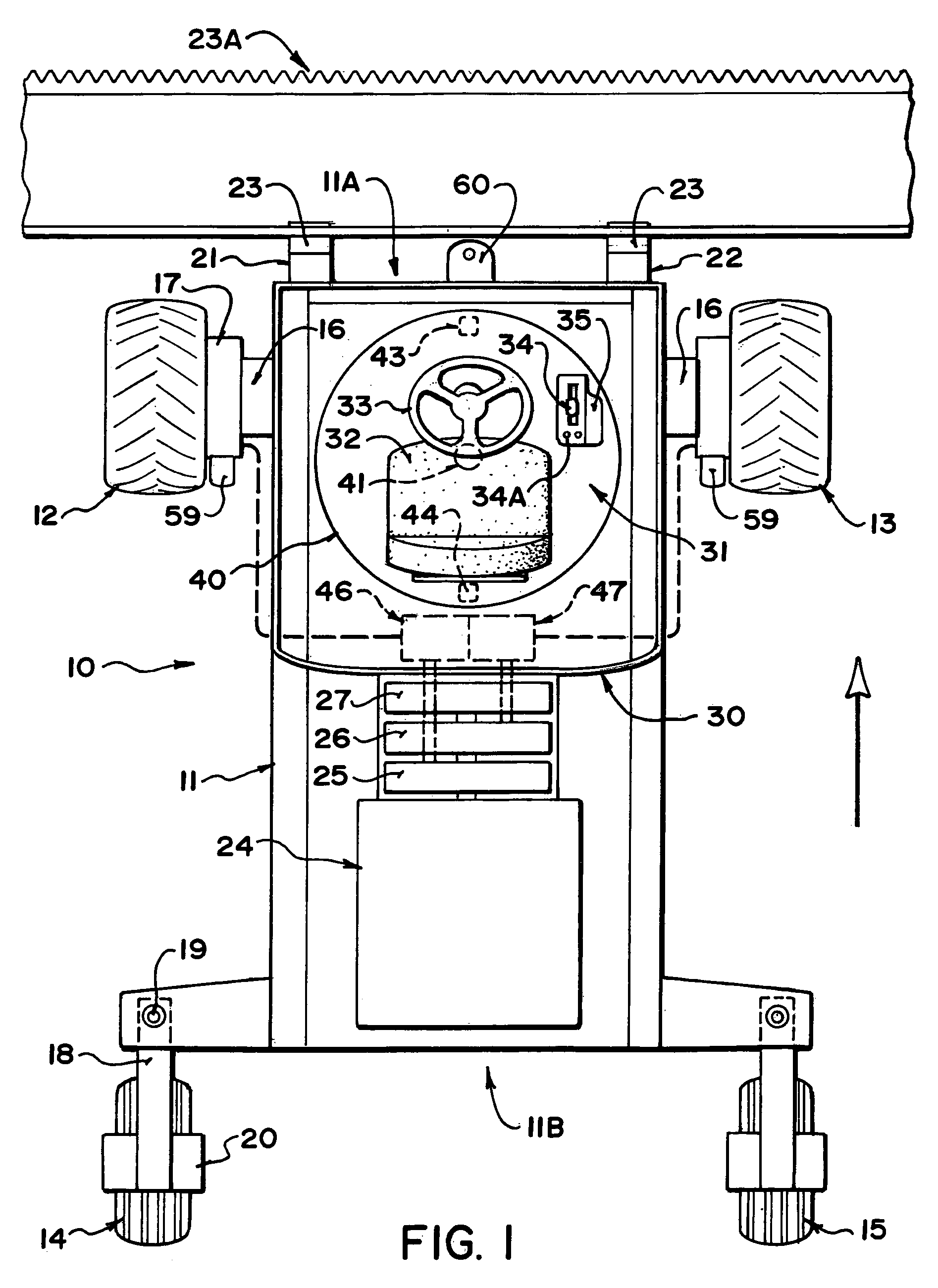
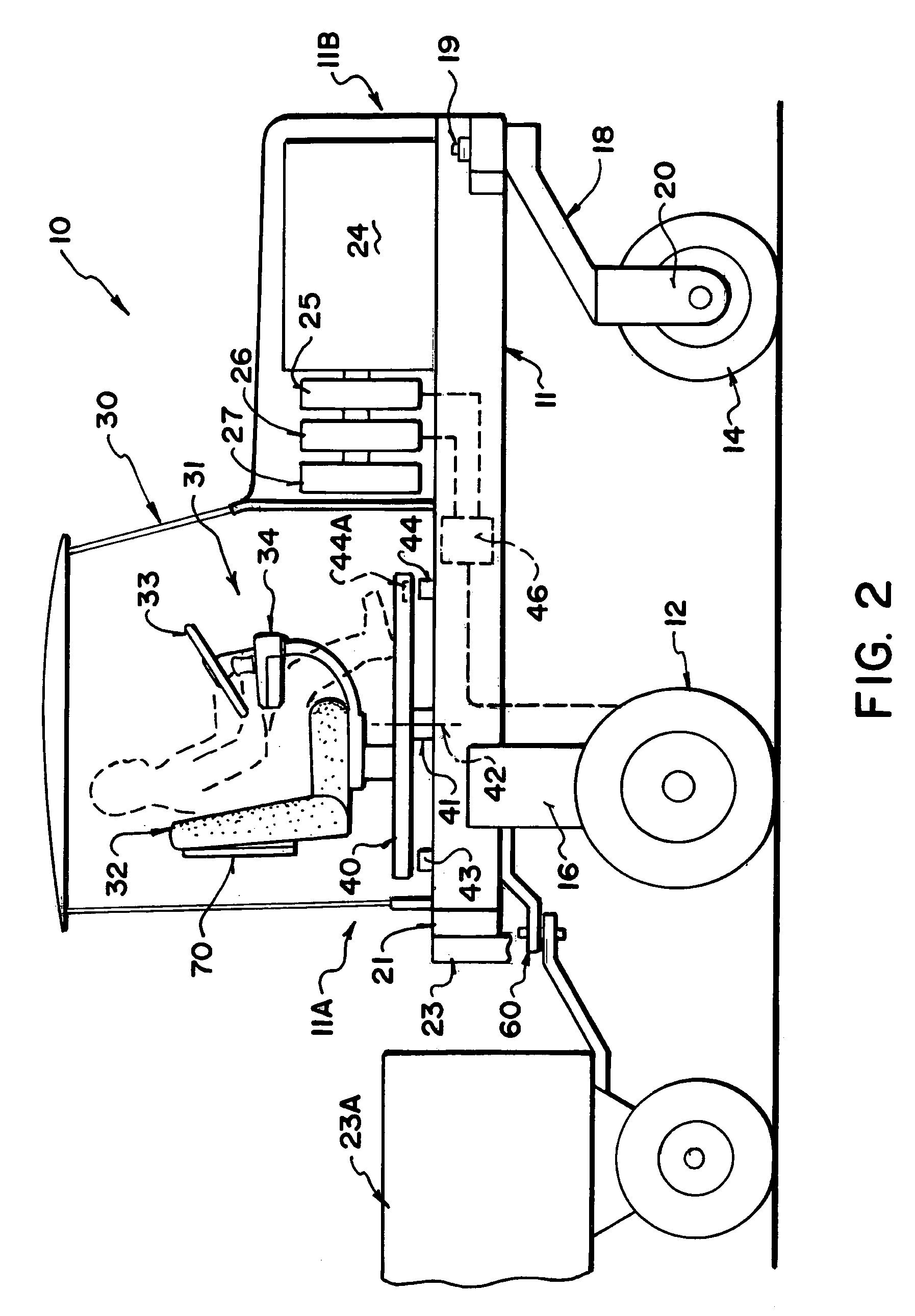
[0068]A swather tractor generally indicated at 10 includes a frame 11 which is carried on a first pair of driven ground wheels 12 and 13 and on a second pair of non-driven castor wheels 14 and 15. The driven wheels 12 and 13 are mounted on suitable supports 16 which support the ground wheels from the frame 11. The driven ground wheels 12 and 13 are each driven by a hydraulic motor 17 carried on the support 16 which receives hydraulic fluid under pressure from a supply line and drives the ground wheel at a rate of rotation dependant upon the rate of flow of the hydraulic fluid.

[0069]The wheels 14 and 15 are mounted on conventional castors 18 which swivel about a castor pin 19. The ground wheels 14 and 15 are non driven and are simply mounted in a supporting bracket 20 which can pivot around the castor pin 19 so that the castor wheels follow the movement of the vehicle as controlled by the driven wheels 12 and 13. Thus the speed of the vehicle over the ground is controlled by the rate...


PUM


Abstract

A tractor has hydraulically driven wheels at a cab end and castor wheels at an engine end. It can be driven cab forward in a working mode with a header on the forward end. It is rotated to engine forward in the transport position for more stable higher speed travel. The driver's console is rotated in the cab with the steering and speed control elements moved with the seat for the driver to face forwards and its position is detected by switches. In the engine forward position for transportation, the control system detects the seat position and operates the controls for higher speed drive and to prevent operation of the header. A vehicle emblem SMV is located on the back of the driver's seat so that it is visible to a person behind regardless of the direction of travel.

Description

[0001]This application claims priority under 35 U.S.C. 119 from provisional application Ser. No. 60 / 659,076 filed Mar. 8th, 2005.[0002]This application is related to application Ser. No. 11 / 116,417 filed simultaneously with this application by the same assignee, the disclosure of which is incorporated herein by reference.[0003]This invention relates to a tractor of the type commonly used as a swather tractor which is supported on a pair of hydraulically drive wheels and a pair of castor wheels in which the operators seat and operating console can be rotated about a vertical axis to two opposed positions for cab forward and engine forward operation.BACKGROUND OF THE INVENTION[0004]Hydrostatically steered vehicles have been around for many years and their application to windrowers has been significant. There has been a limit to the transport speed of these windrowers due to instability at high speed with the drive wheels ahead of the castor wheels (cab forward). Higher speeds on the r...

Claims


Application Information

Patent Timeline
Patent Type & Authority Patents(United States)
IPC IPC(8): B60K26/00
CPCB62D49/0685B62D33/0633B60K7/0015
Inventor DUNN, JAMES THOMASMACGREGOR, DONGABRIEL, BRENTBERGMAN, LEONARD
Owner MACDON INDS
Learn More