Electro-optical composite connector, electro-optical composite cable, and network devices using the same

a technology of electrooptical composite cable and connector, which is applied in the direction of optical elements, coupling device connections, instruments, etc., can solve the problems of radio communication speed change, complicated wiring arrangement of devices between communication devices, and radio communication has a problem in the aspect of information security, etc., to achieve the effect of allowing ordinary users to use connectors and the like easily, and allowing deterioration of signals

Inactive Publication Date: 2007-01-09
SONY CORP
View PDF20 Cites 116 Cited by
  • Summary
  • Abstract
  • Description
  • Claims
  • Application Information

AI Technical Summary

Benefits of technology

[0029]Thus, according to the present invention, each of the electro-optical composite plug and the electro-optical composite receptacle are provided with a signal converter for converting the optical signal transmitted through the optical fiber to the electric signal flowing into the power line or the electric signal to the optical signal, the optical signal transmitted through the optical fiber is converted to the electric signal by the electro-optical composite plug or the electro-optical composite receptacle, and the electric signal thus converted is transmitted to an opposing side through the power connecting device and the receiver (or special connecting terminals). This allows deterioration of a signal due to adhering of dust on a ferrule-connecting end face, which is usually seen conventionally, to be suppressed. Accordingly, no special care is needed for handling of the optical fiber, thereby enabling an ordinary user to use the connector and the like easily.
[0030]Further, a problem about the safety relating to usage of laser can be solved.
[0031]According to the present i

Problems solved by technology

The device has complicated arrangement of wiring between the communication devices.
However, the radio communication has a problem in the aspect of information security because of its low directivity.
Additionally, it has a problem such that communication velocity changes depending on atmospheric cond

Method used


Image

  • Electro-optical composite connector, electro-optical composite cable, and network devices using the same
  • Electro-optical composite connector, electro-optical composite cable, and network devices using the same
  • Electro-optical composite connector, electro-optical composite cable, and network devices using the same

Examples


Embodiment Construction

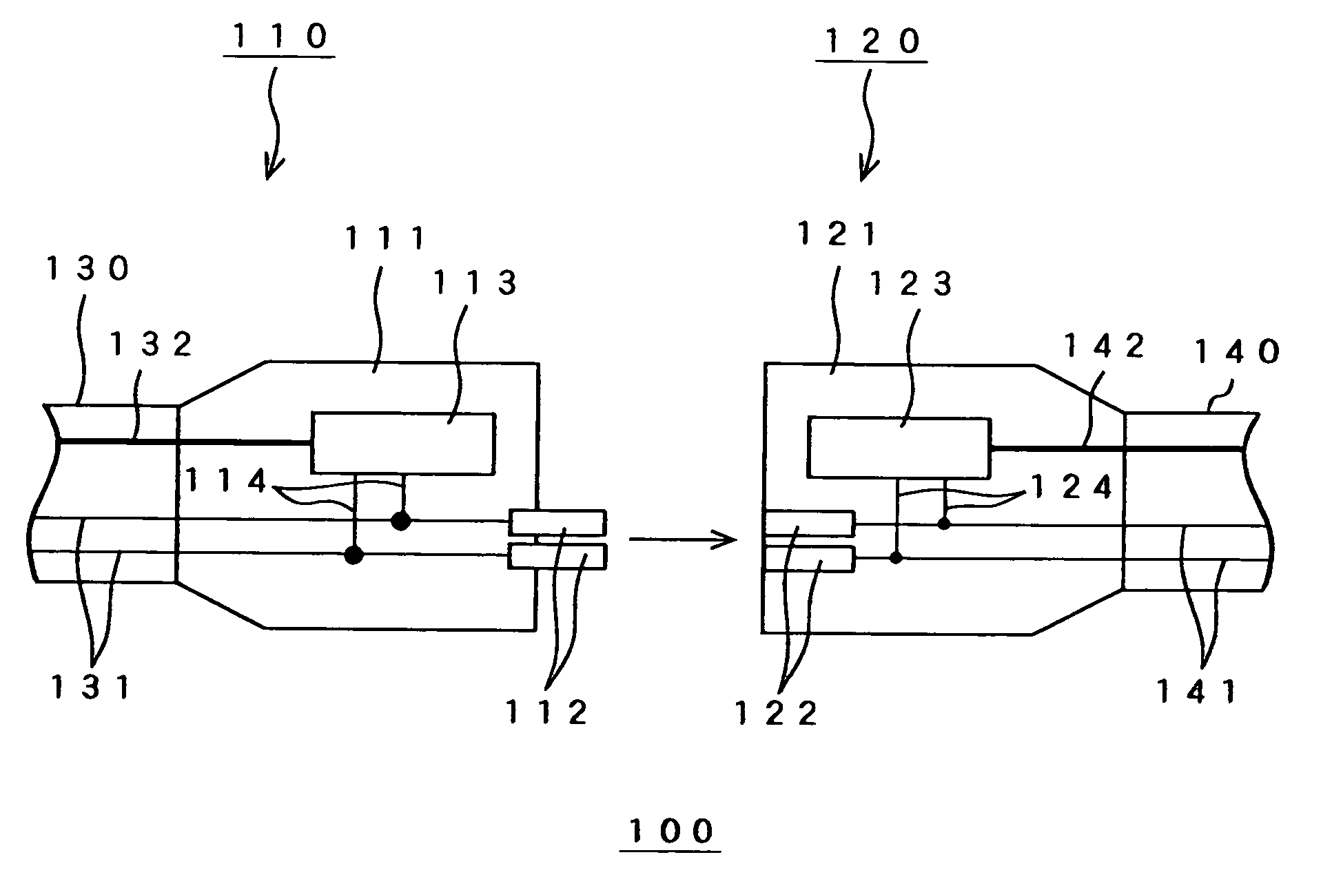
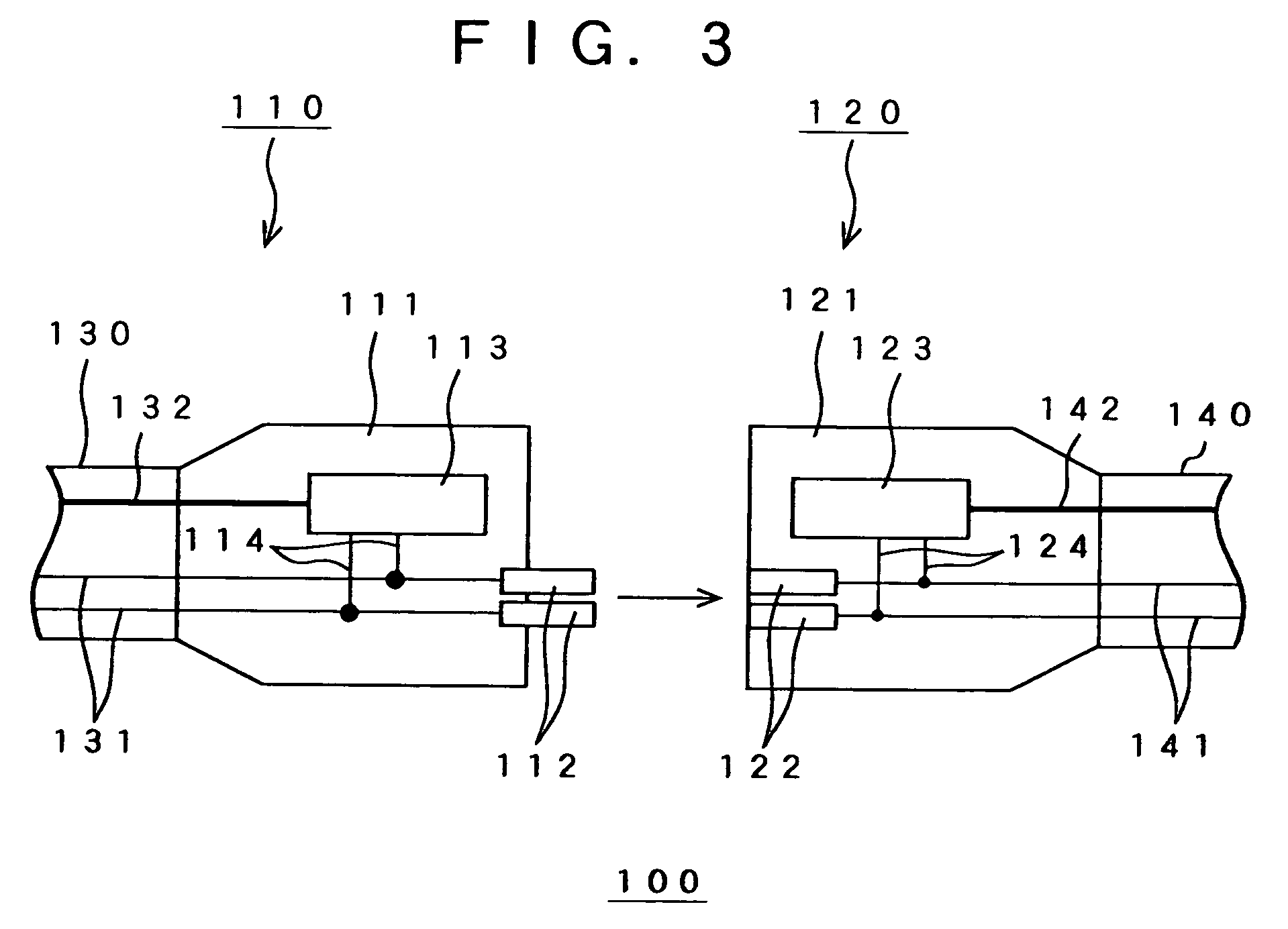
[0042]Hereinafter, a first embodiment of the present invention will be described with reference to the accompanying drawings. FIG. 3 shows a configuration of an electro-optical composite connector 100 according to the first embodiment of the invention.

[0043]As shown in FIG. 3, the electro-optical composite connector 100 comprises an electro-optical composite plug 110 and an electro-optical composite receptacle 120. In the state shown in FIG. 3, a cable 130 is connected to the electro-optical composite plug 110 and a cable 140 is connected to the electro-optical composite receptacle 120. The cable 130 incorporates a power line 131 and an optical fiber 132. The cable 140 also incorporates a power line 141 and an optical fiber 142.

[0044]The electro-optical composite plug 110 comprises a housing 111, a power connecting metal 112, a transceiver 113 which is used as signal converting means, and a lead wire 114.

[0045]The housing 111 is formed in substantially the same configuration as that...


PUM


Abstract

The electro-optical composite connector comprises an electro-optical composite plug and an electro-optical receptacle. The electro-optical composite plug or electro-optical composite receptacle converts an optical signal from an optical fiber to an electric signal and transmits to the opposing electro-optical receptacle or electro-optical composite plug through a power connecting metal or power connecting metal receiver. The opposing electro-optical composite receptacle or electro-optical composite plug converts the electric signal to the optical signal and transmits to the optical fiber.

Description

BACKGROUND OF THE INVENTION[0001]1. Field of the Invention[0002]The present invention relates to a device incorporating power line and information line or the like for transmitting information between information communication devices. Particularly, it relates to an electro-optical composite connector, an electro-optical composite cable and network device using the same.[0003]2. Description of Related Art[0004]Conventionally, a device incorporating power line and information line or the like for transmitting information between information communication devices has been developed. The device has complicated arrangement of wiring between the communication devices. Up to now, radio communication, electric line wiring, electro-optical composite cable and the like have been proposed to solve the problem about complexity between the information communication devices.[0005]However, the radio communication has a problem in the aspect of information security because of its low directivity. ...

Claims


Application Information

Patent Timeline
IPC IPC(8): G02B6/38G02B6/36G02B6/32G02B6/42H01R13/46H01R13/66H01R25/00
CPCG02B6/4201H01R13/665G02B6/4292G02B6/4246G02B6/4284A47G9/10A47G2009/1018
Inventor NAGASHIMA, ZENYAKANEHIRA, HIROKIWATANABE, YOSHIAKI
Owner SONY CORP
Why Eureka
Try Eureka