

Continuously variable transmission and method of operation thereof
a transmission and variable technology, applied in the direction of clutches, mechanical equipment, transportation and packaging, etc., can solve the problems of large biasing force, inability to adjust the speed of the variator,
- Summary
- Abstract
- Description
- Claims
- Application Information
AI Technical Summary
Benefits of technology
Problems solved by technology
Method used
Image

Examples
Embodiment Construction
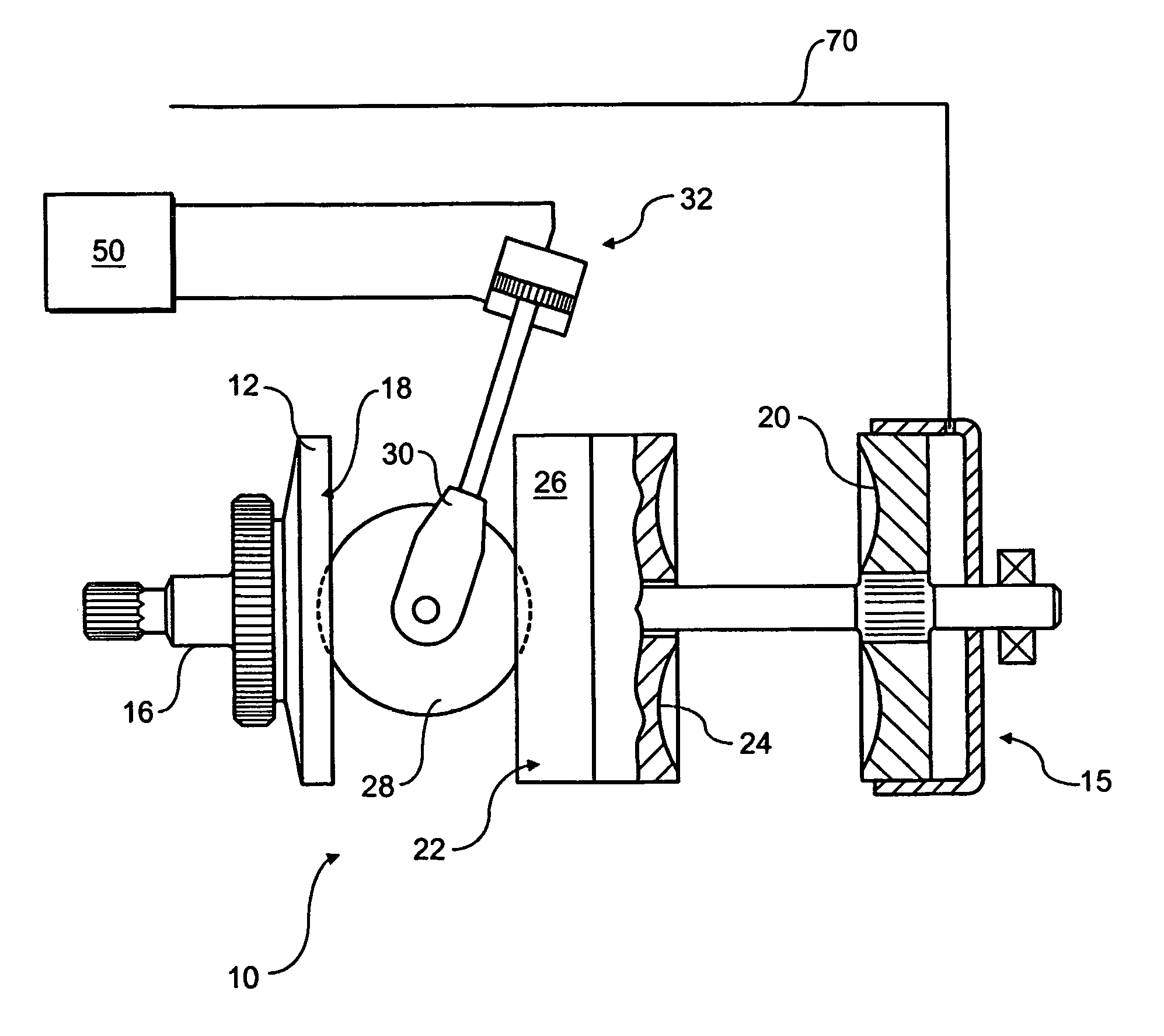
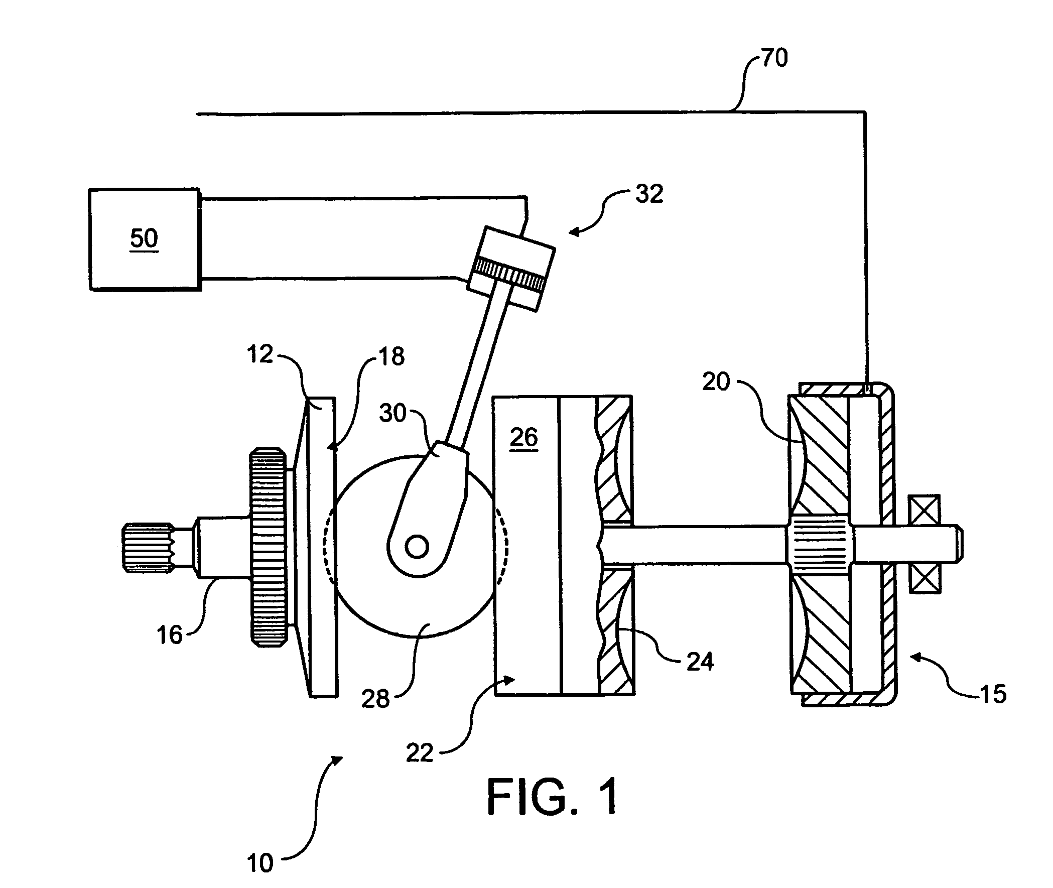
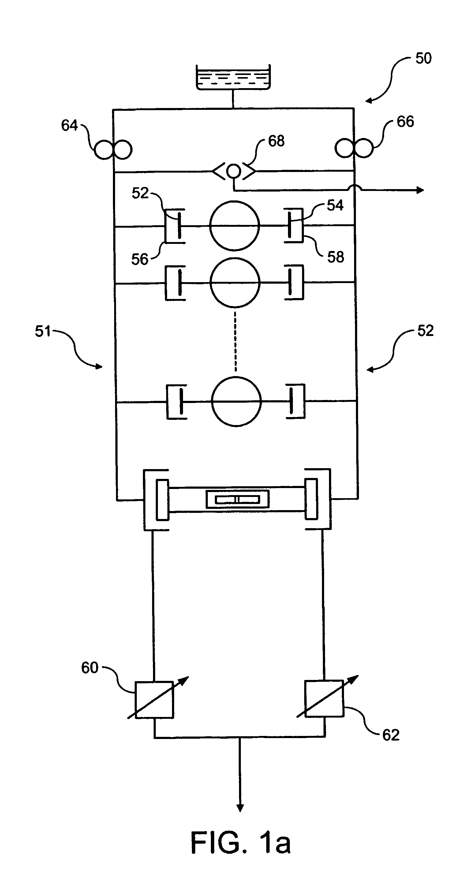
[0048]This embodiment has the advantage that the flow path from the first supply means to the clutch need only contain one valve—the first valve.
[0049]The required pressure signal is preferably taken from the second supply means. Still more preferably, the pressure signal is opposed by a further pressure signal taken from the clutch, such that as clutch pressure rises the first valve is caused to shuttle back to connect the clutch to the second supply means.
[0050]Adjustment of the fluid pressure applied to the clutch from the second supply means is preferably carried out in dependence upon transmission parameters. An electronic control unit (“ECU”) preferably monitors the relevant parameters and sets the fuse pressure.
[0051]The effect is preferably to adjust the pressure from the second supply means in dependence upon torque demand. In a multi-regime transmission this may be achieved by controlling the pressure—and hence the clutch torque capacity—as a function of transmission regim...
PUM
 Abstract
Description
Claims
Application Information