Mist elimination hood
a technology of elimination hood and hood, which is applied in the direction of electrode cleaning, dispersed particle separation, separation process, etc., can solve the problems of droplet re-entrainment and carry-over, pad often suffering plugging problems, and plugging problems, so as to prevent liquid droplet carry-over
- Summary
- Abstract
- Description
- Claims
- Application Information
AI Technical Summary
Benefits of technology
Problems solved by technology
Method used
Image
Examples
example 1
[0025]This Example illustrates the results obtained using a laboratory scale WESP structure.
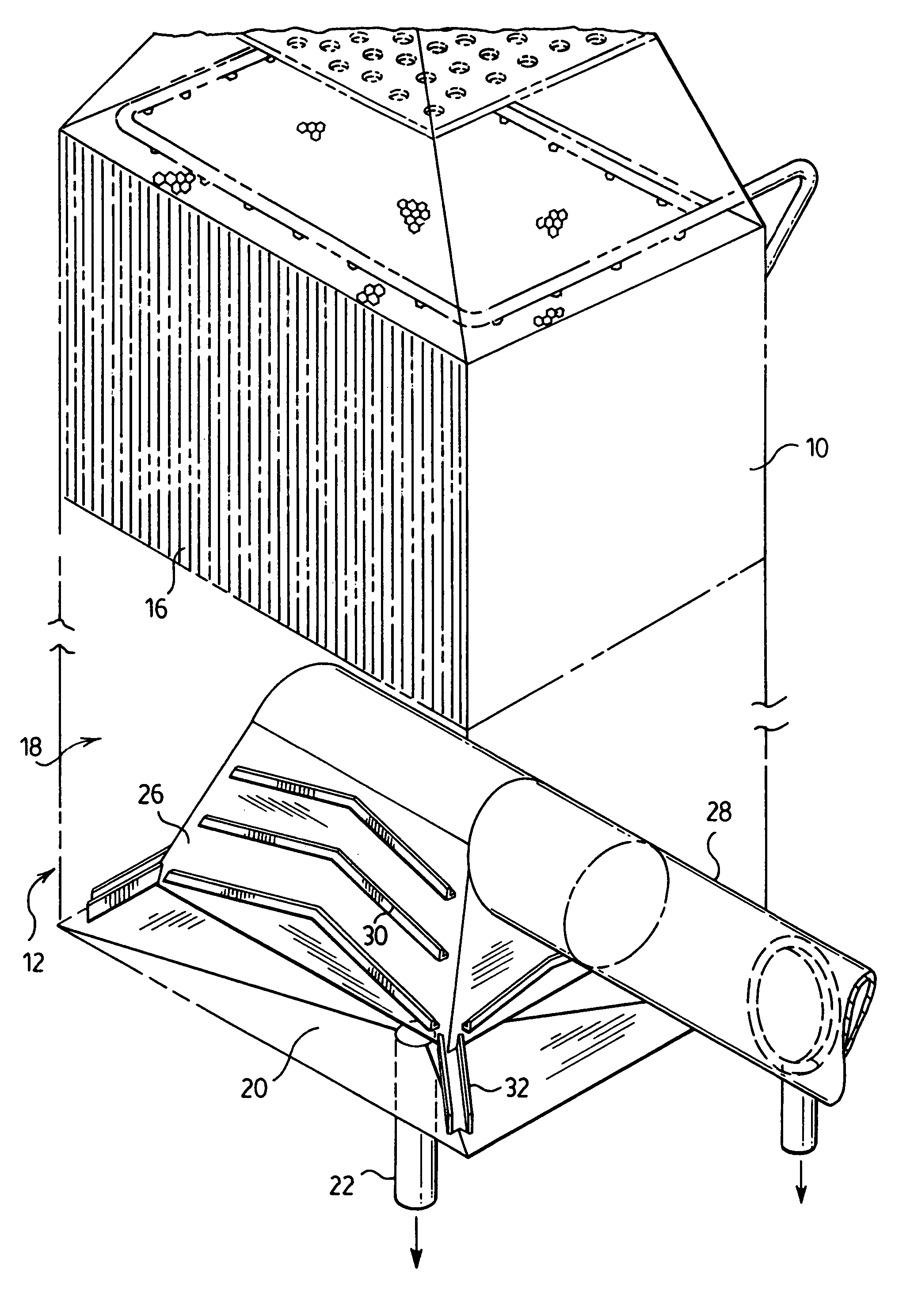
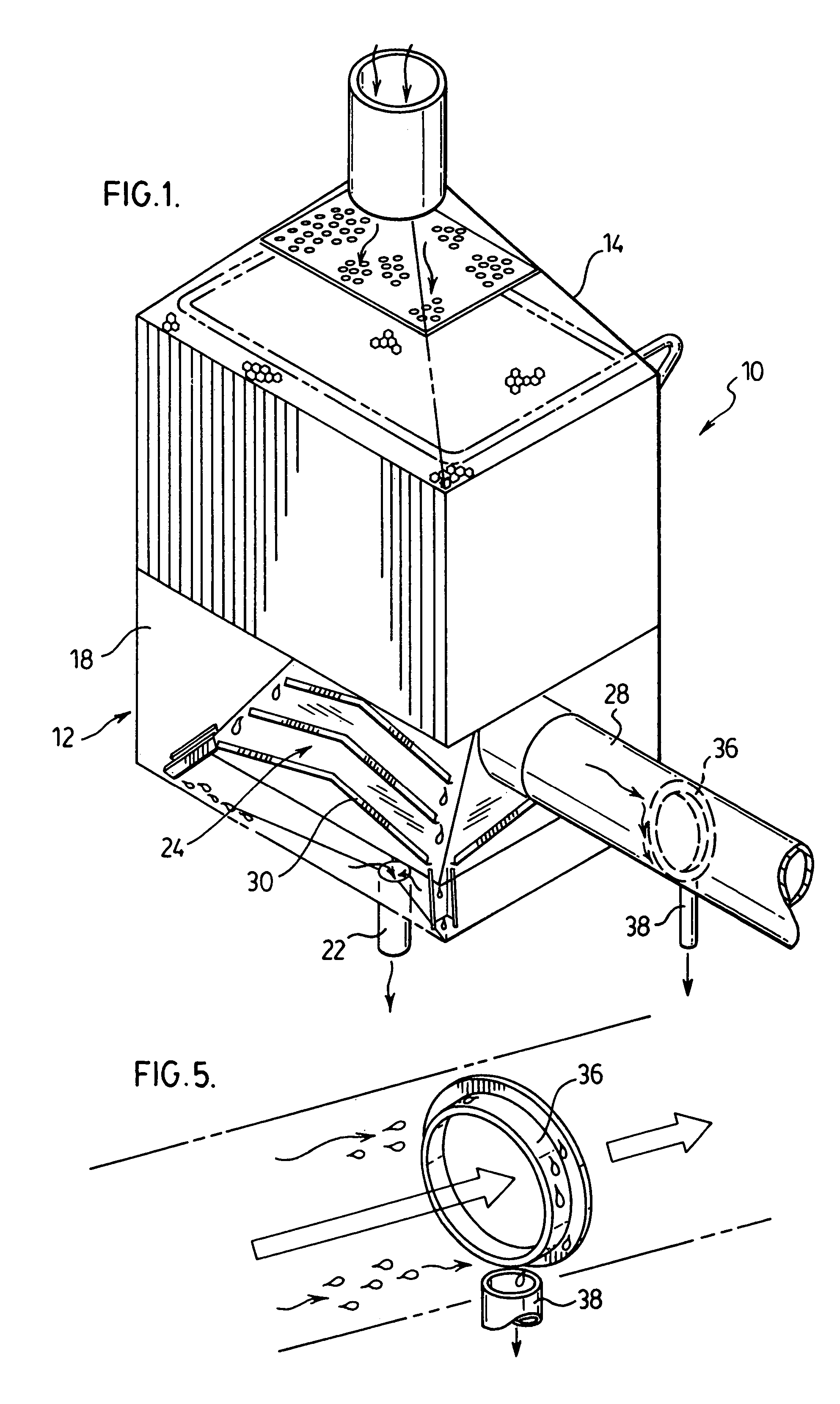
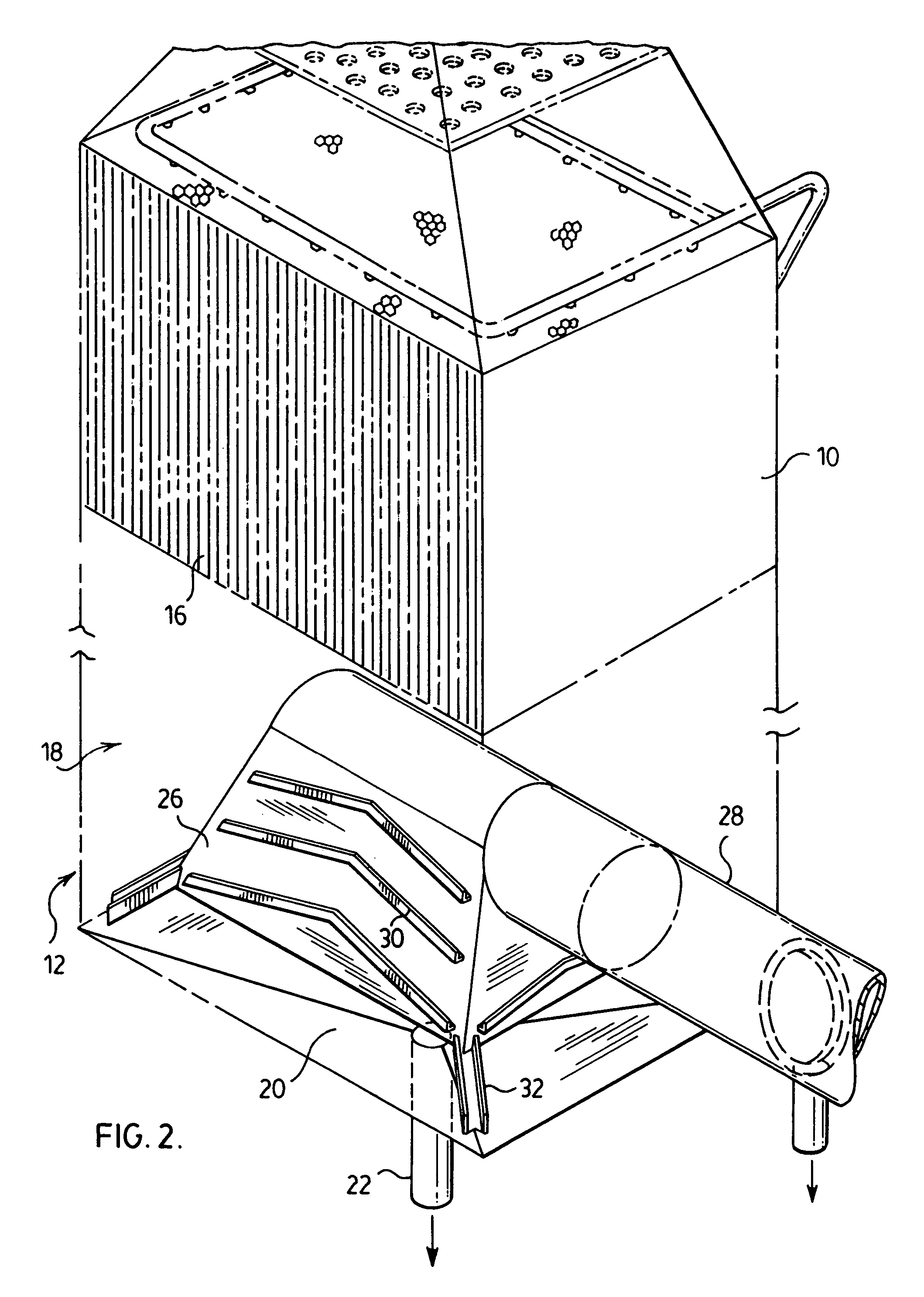
[0026]A ⅛ scale model of a commercial rectangular cross-section WESP structure was set up as illustrated in FIGS. 1 to 5. The model extended from the WESP inlet, through the collection tubes and into the outlet hood and duct. The humidification spray nozzle was simulated using a single multi-orifice air atomized spray nozzle operated at 50 to 60 psi to ensure good atomization and fine droplet size.
[0027]In the absence of the gutters provided in the hood, there was strong visual evidence of a significant amount of water being carried into the outlet duct, particularly during a tube wash operation. However, with the addition of the water collection gutters to the outside of the hood, the amount of liquid observed to be carried over was significantly reduced.
[0028]The liquid carryover was determined by droplet counters and the average carryover was 0.000764 US gpm / ft2. With the wash spray on, th...
example 2
[0030]This Example illustrates the results obtained using a further laboratory scale WESP structure.
[0031]A ⅙ scale model of a circular cross-section WESP structure was set up as illustrated in FIGS. 6 to 8, with the gutters in place. The model extended from the horizontal inlet duct through the WESP vessel to the outlet duct. The humidification spray nozzle was a single multiple-orifice air-atomized spray nozzle operated at 50 psig to ensure good atomization and fine droplet size with a mean of 27 microns.
[0032]The WESP flush sprays were simulated by a 8 Bete WL-1 / 4 60 degree hydraulic nozzles mounted on a ring header at equal spaces. During wash simulation, the header was operated at a flow rate of 6 usgpm at approximately 10 psig.
[0033]The liquid carryover to the outlet duct was determined by droplet counters. With only the inlet spray operating, the carryover was 4.43×10⁻¹⁰ usgpn / ft2 with an average droplet size in the outlet duct of 3.2 microns. With only the flush sprays opera...
example 3
[0035]This Example illustrates the results obtained using a plant scale WESP structure.
[0036]A rectangular full scale mist eliminator hood structure as illustrated in FIGS. 1 to 5 was installed to replace an existing mesh pad arrangement which was causing operational problems due to plugging and free moisture carryover from the WESP.
[0037]The installation reduced moisture carryover to values below detection as measured using EPA Method 5 and has been operating for more than eight months without maintenance or interfering with production.
PUM
| Property | Measurement | Unit |
|---|---|---|
| sizes | aaaaa | aaaaa |
| droplet size | aaaaa | aaaaa |
| droplet size | aaaaa | aaaaa |
Abstract
Description
Claims
Application Information
 - R&D
- Intellectual Property
- Life Sciences
- Materials
- Tech Scout
- Unparalleled Data Quality
- Higher Quality Content
- 60% Fewer Hallucinations
Browse by: Latest US Patents, China's latest patents, Technical Efficacy Thesaurus, Application Domain, Technology Topic, Popular Technical Reports.
© 2025 PatSnap. All rights reserved.Legal|Privacy policy|Modern Slavery Act Transparency Statement|Sitemap|About US| Contact US: help@patsnap.com


