Device and method for measuring capacitance and device for determining the level of a liquid using one such device

a capacitance and liquid level technology, applied in liquid/fluent solid measurement, machines/engines, instruments, etc., can solve the problems of high production and installation costs, achieve continuous reliable operation, improve the resolution and (in)sensitivity to noise signals, and improve the effect of production and installation

Inactive Publication Date: 2007-01-09
HYDAC ELECTRONICS GMBH
View PDF3 Cites 28 Cited by
  • Summary
  • Abstract
  • Description
  • Claims
  • Application Information

AI Technical Summary

Benefits of technology

[0004]An object of the present invention is to provide an improved device, process and corresponding means for determining the level of a liquid in a container. Other objects of the device of the present invention are to be especially economical to produce and install, and to be continuously reliable in operation. Resolution and (in)sensitivity to noise signals are to be further optimized.
[0008]The tube, on its side facing the liquid, can be provided at least partially, preferably over its entire surface area, with a coating. As a result of the material chosen for the coating, for example, a high beading effect of the liquid is caused, and therefore, reduces wetting with the liquid, and / or prevents diffusion of the liquid into the tube. These coatings may contain, for example, a polymer plastic, and can be applied to the tube by painting or by an immersion bath.
[0015]In one special embodiment of the present invention, the definable reference potential is the ground potential of the measurement means. In this way, the capacitance values of the switched electrodes can be measured especially easily in terms of circuitry and at the same time with a high degree of precision.
[0017]Preferably, all electrodes not switched as measurement electrodes are switched to the reference potential, to the ground potential in particular. In the case of a level sensor, it is moreover advantageous to switch the liquid and / or at least one part of the wall of the container to this or another definable reference potential.
[0018]All electrodes preferably have an essentially identical contour and surface area. Preferably, all electrodes are arranged essentially equidistantly relative to one another and / or to the connecting lines. This arrangement yields not only simplified production of the device, but the measured capacitance values and capacitance changes are also fundamentally of the same order of magnitude. When switching through in alternation, it is moreover advantageous that the reliability of the device is increased due to the fact that the electrodes are identical. Moreover, the elongated reference potential electrode with a large surface area is not necessary in the present invention. Such lacking requirement clearly reduces the surface area required by the electrode arrangement, or the electrodes can be larger with the same required surface area, whereby the measurement sensitivity and / or the measurement accuracy is increased.
[0019]To increase the measurement accuracy at a given overall size of the device, it is also possible for several electrodes, which are preferably not directly adjacent, to be interconnected hard-wired into one respective electrode group. Each electrode group is alternately switched as a measurement electrode. At least one of the other respective electrode groups is switched as the counterelectrode to the definable reference potential by the switching device. This arrangement corresponds to dividing the individual electrodes into different component segments. The hard-wired interconnection of the electrodes into the respective electrode group takes place preferably at the location of the connecting lines, especially at the height of the pertinent electrode, so that the demand for space is not increased either with respect to the connecting lines.

Problems solved by technology

These devices necessitate high complexity of interconnection, and thus, high production and installation costs.

Method used


Image

  • Device and method for measuring capacitance and device for determining the level of a liquid using one such device
  • Device and method for measuring capacitance and device for determining the level of a liquid using one such device
  • Device and method for measuring capacitance and device for determining the level of a liquid using one such device

Examples


Embodiment Construction

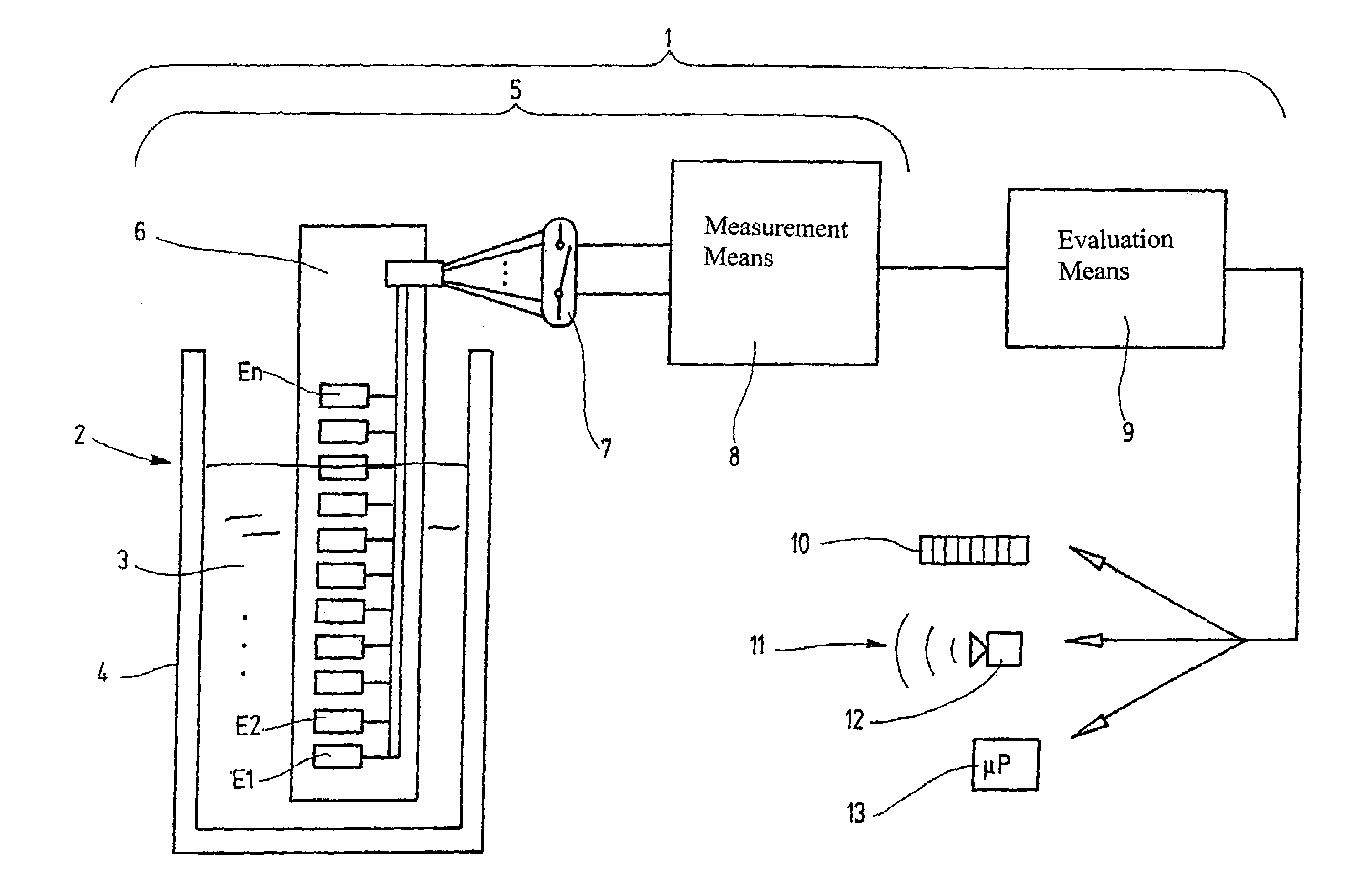
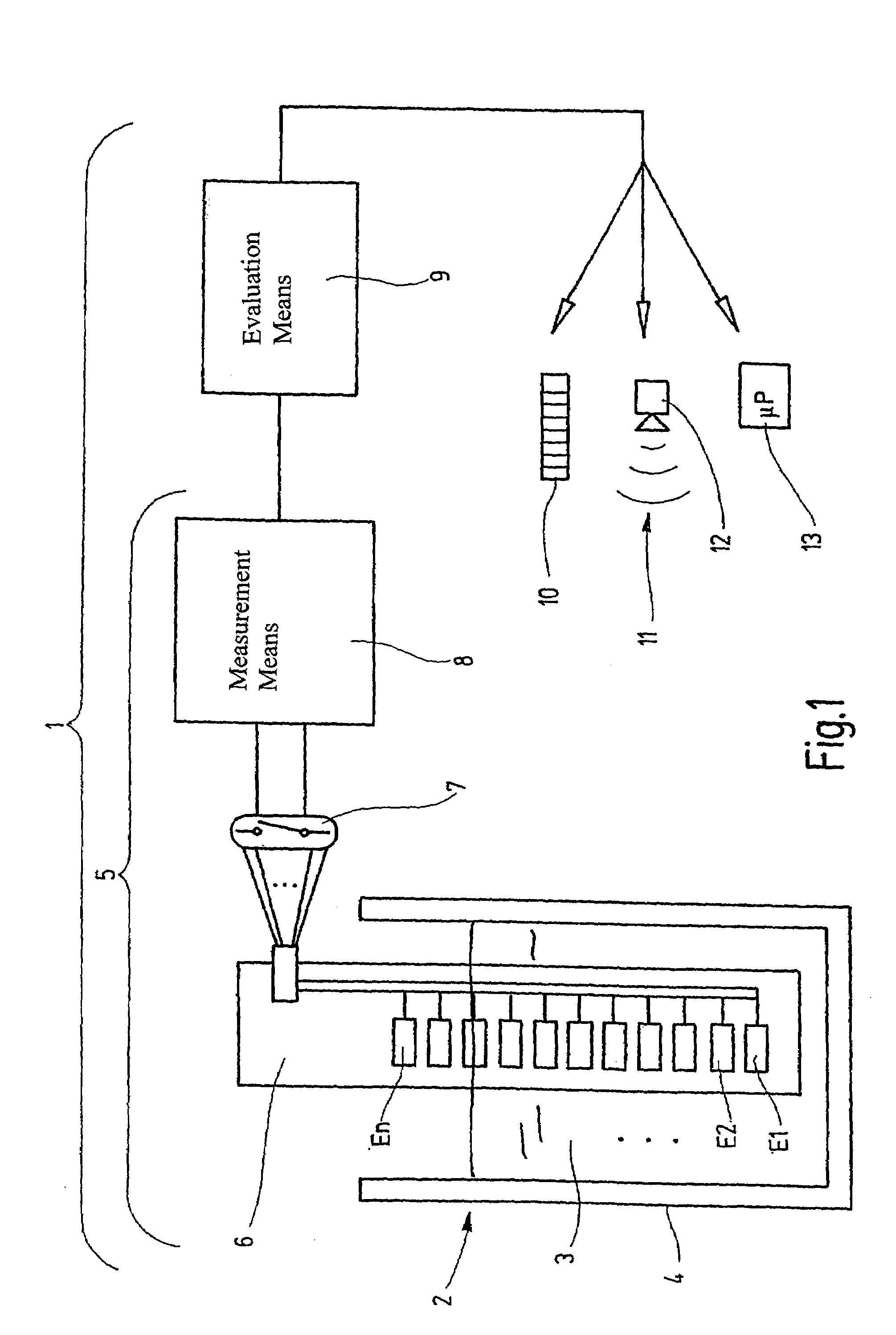
[0032]FIG. 1 shows in a simplified representation a means 1 according to an embodiment of the present invention for determining the level 2 of a liquid 3 in a container 4 with the device 5. The device 5, according to an embodiment of the present invention, measures the capacitance with an electrode arrangement having a plurality of electrodes E1 to En arranged in succession on a support 6. The device 5 furthermore has its own measurement means 8 for measurement of the capacitance between the first electrode E2 as the measurement electrode and the second electrode E1 as the counterelectrode. Also, the device 5 has a controllable switching means 7 for connection of the electrodes E1 to En as the first and second electrodes E2 and E1 to the measurement means, which connection can be switched in a definable manner.

[0033]The means 1 for determining the level 2 of liquid 3 furthermore comprises an evaluation means 9 downstream of the measurement means 8. Evaluation means 9 determines the ...


PUM


Abstract

A device (5) measures capacity, and includes an electrode arrangement with a plurality of electrodes (E1, E2, . . . , En) which are adjacently and / or successively arranged on a carrier (6). An intrinsic measuring device (8) measures the capacitance between a first electrode (E2), in the form of a measuring electrode, and a second electrode (E1), in the form of a counter-electrode. A controllable switching device (7) connects the electrodes (E1, E2, . . . , En), in the form of first and second electrodes (E2, E1), to the measuring device (8) in such a way that they can be switched in a pre-determinable manner. Each electrode (E1, E2, . . . , En) of the electrode arrangement can be switched in a controlled, alternate manner by the switching device (7), in the form of a measuring electrode, and respectively at least one of the other electrodes (E1, E2, . . . , En), in the form of a counter-electrode, can be switched to a pre-determinable reference potential. An associate method and a device (1) determine the level (2) of a liquid (3) using one such device (5).

Description

FIELD OF THE INVENTION[0001]The present invention relates to device for measuring capacitance with a plurality of electrodes mounted on a support located next to one another or in succession, and a corresponding method and a device for determining the level of a liquid using such device.BACKGROUND OF THE INVENTION[0002]The prior art, for example, the publication of TOTH, F. N. et al.: A new capacitive precision liquid-level sensor, Digest 1996 Conference on Precision Electromagnetic Measurements, Braunschweig, discloses generic devices. Elongated “guard” and reference potential (“E0”) electrodes are located parallel to a series of successive measurement electrodes adjacently on one side or both sides. The capacitance, and thus, ultimately the level are measured by measuring the capacitance between the individual measurement electrodes and the opposing elongated reference potential electrode.[0003]These devices necessitate high complexity of interconnection, and thus, high production...

Claims


Application Information

Patent Timeline
Patent Type & Authority Patents(United States)
IPC IPC(8): G01R27/26G01F23/26
CPCG01F23/268G01F23/265
Inventor QU, WENMINGAMEL, JULIEN FREDERICMANNEBACH, HORSTJIRGAL, LEO MATHIAS
Owner HYDAC ELECTRONICS GMBH
Why Eureka
Try Eureka