Ported loudspeaker system and method with reduced air turbulence, bipolar radiation pattern and novel appearance

a loudspeaker and air turbulence technology, applied in the field of loudspeaker systems, can solve the problems of ineffective operation or operation, ineffective realization or operation of the intended function, and ineffective optimization of the theoretical design, so as to reduce the transmission of midrange frequencies, improve the porting arrangement, and reduce the turbulence and loss

Inactive Publication Date: 2007-01-09
POLK AUDIO LLC
View PDF12 Cites 31 Cited by
  • Summary
  • Abstract
  • Description
  • Claims
  • Application Information

AI Technical Summary

Benefits of technology

[0013]It is an object of this invention to provide an improved porting arrangement and method for use in a loudspeaker system with reduced turbulence and loss, reduced transmission of midrange frequencies and less audible organ pipe resonances.
[0014]It is another object of this invention to provide an efficient port structure with a novel appearance which is more compact, simpler to implement and which has a bipolar radiation pattern.
[0015]Briefly and in accordance with one embodiment of the present invention, a first port is provided in the speaker baffle of the loudspeaker system with a predetermined length extending inwardly into the speaker cabinet. A second port is provided in the opposite wall of the loudspeaker enclosure from the speaker baffle of similar cross-section to the first port with a predetermined length extending inwardly into the speaker cabinet toward the first port and aligned on a common axis with the first port such that the inward ends are separated by a predetermined separation distance inside the loudspeaker enclosure and such that the two ports together appear to provide an unobstructed open duct passing entirely through the loudspeaker cabinet from front to back. The additional acoustic mass required to achieve a desired tuning frequency is provided by flanges of a predetermined diameter, greater than the ports, affixed concentrically to the inward end of each of the ports and separated by a predetermined separation distance. The two flanges or disks provide a circumferential extension of the internal separation distance between the two ports. The effect of this arrangement is to provide an increasing cross-sectional area at the inside end of the port structure for the purpose of reducing turbulence and loss. Mid-range transmission from the interior of the loudspeaker cabinet is suppressed since higher frequencies will tend to pass through the separation between the two ports with very little midrange energy escaping through the ports to the exterior of the loudspeaker cabinet. The principle organ pipe resonance due to the combined length of the ports is also suppressed due to the separation distance between the two ports. Due to the front and back openings, the port structure of the present invention will also have a radiation pattern which is approximately bipolar at low frequencies. Bipolar radiation of sound refers to the radiation of in-phase acoustic energy from both front and back of a loudspeaker system in similar but not necessarily equal amounts. Bipolar radiation of sound is believed to result in a more even distribution of low frequency energy into the listening area. In addition, the two port openings provide a larger cross-sectional area which further reduces turbulence and loss. Finally, the illusion of an unobstructed duct passing entirely through the loudspeaker enclosure presents a novel appearance.

Problems solved by technology

However, practical considerations often prevent these designs, optimized in theory, from being realized in actuality or from functioning as intended.
There are, however, disadvantages to the ducted port approach.
These relate principally to undesirable noise and attendant losses which may be generated by the port at the higher volume velocity of air movement required to produce higher low frequency sound pressure levels.
However a small cross-section is in conflict with the larger volume velocities of air required to reproduce higher sound pressure levels at lower frequencies.
For example, if the diameter of a port is too small or is otherwise improperly designed, non-linear behavior such as chuffing or port-noise due to air turbulence can result in audible distortions and loss of efficiency at low frequencies particularly at higher levels of operation.
In addition, viscous drag from air movement in the port can result in additional loss of efficiency at lower frequencies.
The required increase in length, however, may be impractical to implement.
Other difficulties may also arise as the length of the port and cross-section are increased.
These organ pipe resonances may produce easily audible distortion when they occur within certain ranges of frequencies.
In addition, a larger cross-sectional area may lead to undesirable transmission of mid-range frequencies generated inside the enclosure to the outside of the enclosure.
This may also lead to audible distortion in the form of frequency response variations due to interference with the direct sound produced by the loudspeaker system.
Therefore, the design of ports for vented loudspeaker systems involves conflicting requirements.
A large cross-sectional area is required to avoid audible noise and losses due to non-linear turbulent flow but this makes it difficult to achieve the acoustic mass required for a low tuning frequency within practical size constraints.
The increased cross-section of the flare may increase the transmission of undesirable midrange frequencies from inside the loudspeaker cabinet and an improperly selected rate of flare may actually increase turbulence.
As discussed above this may lead to impractical length requirements and more audible organ pipe resonances.

Method used


Image

  • Ported loudspeaker system and method with reduced air turbulence, bipolar radiation pattern and novel appearance
  • Ported loudspeaker system and method with reduced air turbulence, bipolar radiation pattern and novel appearance
  • Ported loudspeaker system and method with reduced air turbulence, bipolar radiation pattern and novel appearance

Examples


Embodiment Construction

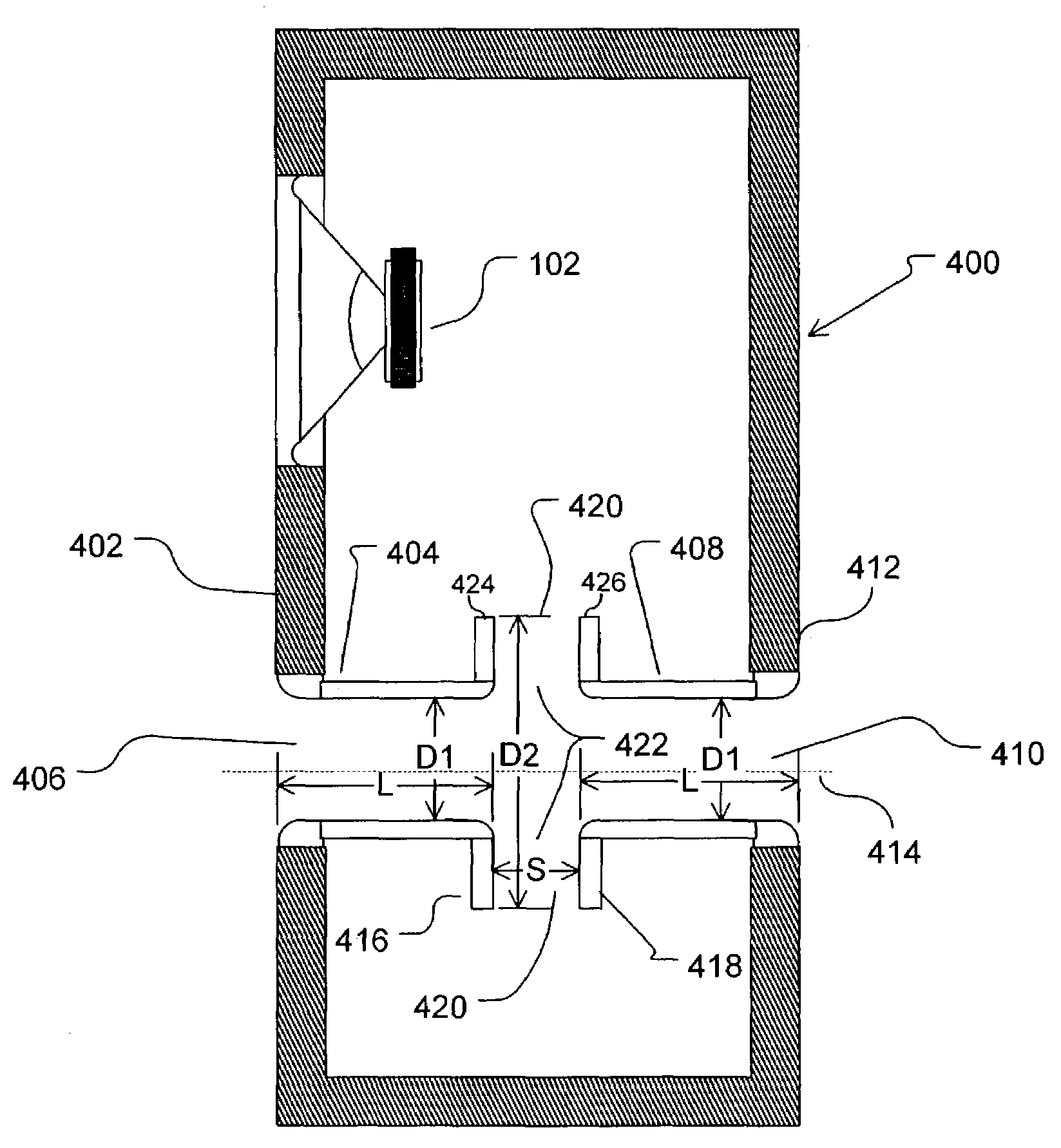
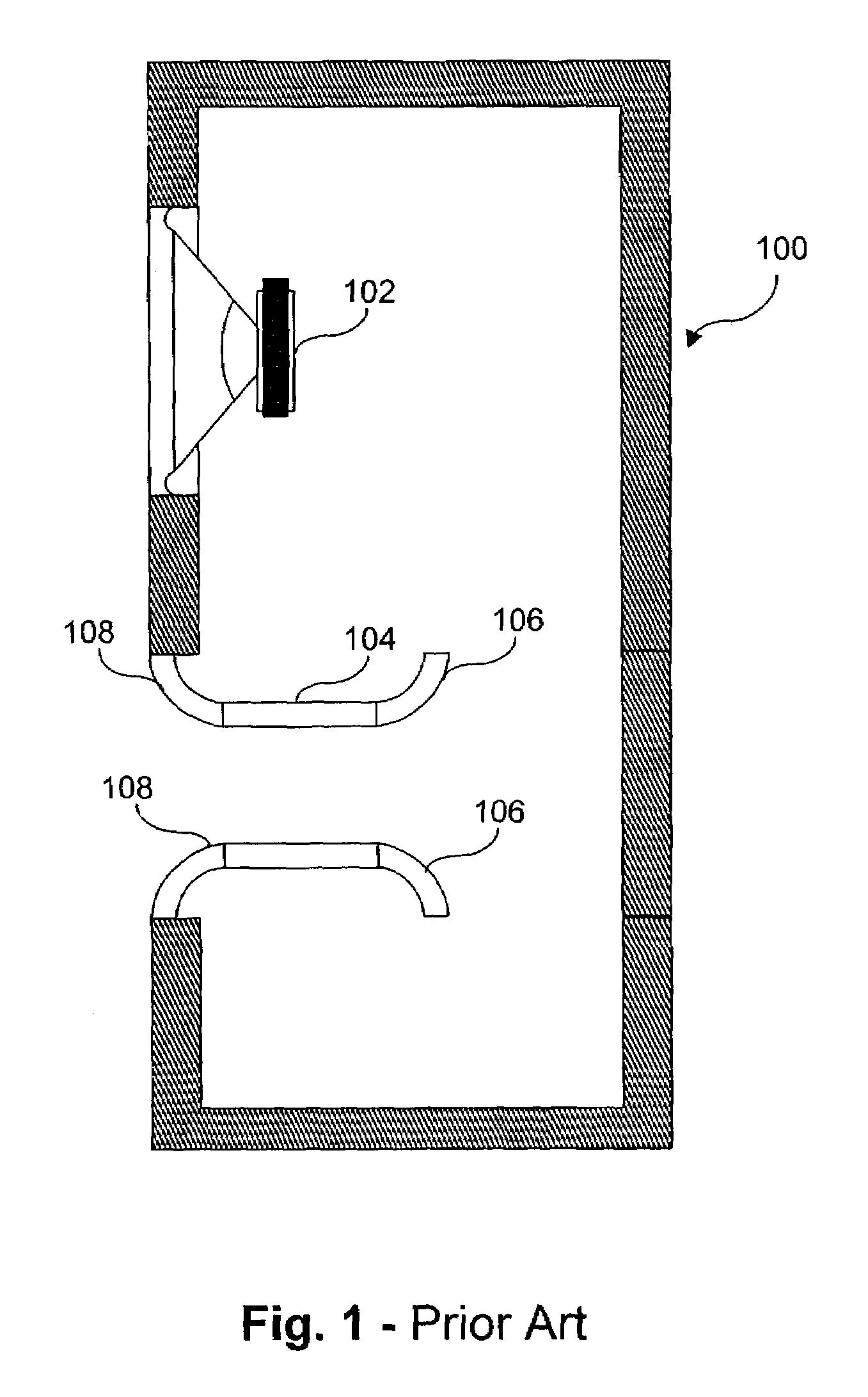
[0022]As discussed above, there are various tradeoffs involved in the design of ducted ports for a loudspeaker system. Increases in cross-sectional area required to reduce turbulence and loss require increases in port length to achieve the required acoustic mass. The increased port length may be too large for the system dimensions and may also lead to organ pipe resonances at frequencies more likely to cause audible problems. Use of flared ends as part of the port structure, as shown in FIG. 1, may reduce turbulence and loss for a given cross-sectional area in the central part of the port, but the flared ends themselves contribute little to the required acoustic mass while making the port structure substantially larger. As noted above, U.S. Pat. Nos. 5,517,573 and 5,809,154 to Polk, et al. disclose a porting method and arrangement for reducing turbulence and loss which is more compact and offers certain other advantages in suppressing unwanted midrange transmission and organ pipe re...


PUM


Abstract

A loudspeaker system includes a cabinet with an interior air volume, a transducer, a first port extending from an opening in the front wall of the cabinet to the interior of the cabinet, and a second port extending from and opening in the rear wall of the cabinet to the interior of the cabinet. The first and second ports are aligned along a common longitudinal axis and the interior ends of the ports are separated from each other by a predetermined distance. First and second flanges having a diameter larger than the first and second ports are disposed at the interior ends of the first and second ports, respectively.

Description

CROSS-REFERENCE TO RELATED APPLICATIONS[0001]Not ApplicableBACKGROUND OF THE INVENTION[0002]1. Field of the Invention[0003]This invention relates generally to loudspeaker systems and in particular relates to an improved loudspeaker having a unique port or vent geometry together with a corresponding method of porting a loudspeaker in an efficient manner and with a novel appearance.[0004]2. Related Art[0005]Vented box loudspeaker systems have been popular for at least 50 years as a means of obtaining greater low frequency efficiency from a given cabinet volume. Significant advances were made in understanding and analyzing vented loudspeaker systems through the work of Thiele and Small during the 1970's. Since then, readily available computer programs have made it possible to easily optimize vented loudspeaker designs. However, practical considerations often prevent these designs, optimized in theory, from being realized in actuality or from functioning as intended.[0006]There are two ...

Claims


Application Information

Patent Timeline
Patent Type & Authority Patents(United States)
IPC IPC(8): H04R1/28
CPCH04R1/2826H04R1/2819
Inventor POLK, JR., MATTHEW S
Owner POLK AUDIO LLC
Why Eureka
Try Eureka