
Data recording apparatus, medium and information package

a technology of data recording and data, applied in the field of data recording apparatus, can solve the problems of noise, storage data may include noise, and subsequent image data must be abandoned,

Inactive Publication Date: 2007-01-09
PANASONIC CORP
View PDF9 Cites 14 Cited by
  • Summary
  • Abstract
  • Description
  • Claims
  • Application Information

AI Technical Summary

Benefits of technology

[0017]file writing means for writing data in a file according to the control from said file creation controlling means.

Problems solved by technology

(1) The maximum capacity of one file handled by Windows is 2^31 bytes (“^” denotes power), that is, 2 GB. On the contrary, video data in a DV format which is suitable for NTSC format of present TV signal is 120,000 bytes per 1 frame and so when DV data is captured, only data for approximately 9 minutes can be captured even if there is an enough space in the hard disk. Thus, a problem arises that if one file becomes full, subsequent image data must be abandoned. Furthermore, even if the data spilling out of the file is stored in another file, when it is stored in the other file in the middle of a frame, that is, one frame is recorded on different areas noise can occur in the reproduced data.
(2) Furthermore, an animation or voice mode in an AVI file format must be unique within one file. For example, mode information that indicates a voice mode includes a sampling frequency and the sampling frequency must be constant in one AVI file.
Therefore, if such animation is captured in a conventional AVI file format, a problem arises that that when reproduced, the stored data may include noise.
However, when data is converted to an AVI file conventionally, a problem arises that copyright is not taken into account enough.
(4) Furthermore, when the remaining recording capacity of a recording area (normally partition) becomes 0 during capturing, a problem arises that that no more video data can be recorded.
Even if the remaining data is recorded in another recording area, when the recording area is switched in the middle of a frame, that is, one frame is recorded on different areas, a problem arises that that noise can be generated when the data is reproduced.

Method used


Image

  • Data recording apparatus, medium and information package
  • Data recording apparatus, medium and information package
  • Data recording apparatus, medium and information package

Examples


first embodiment

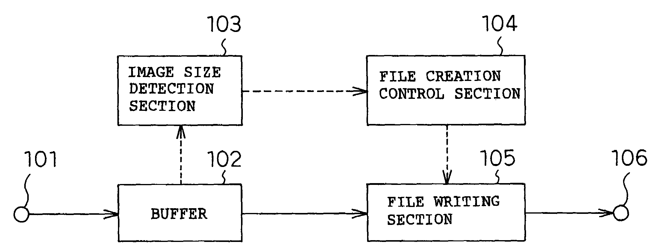
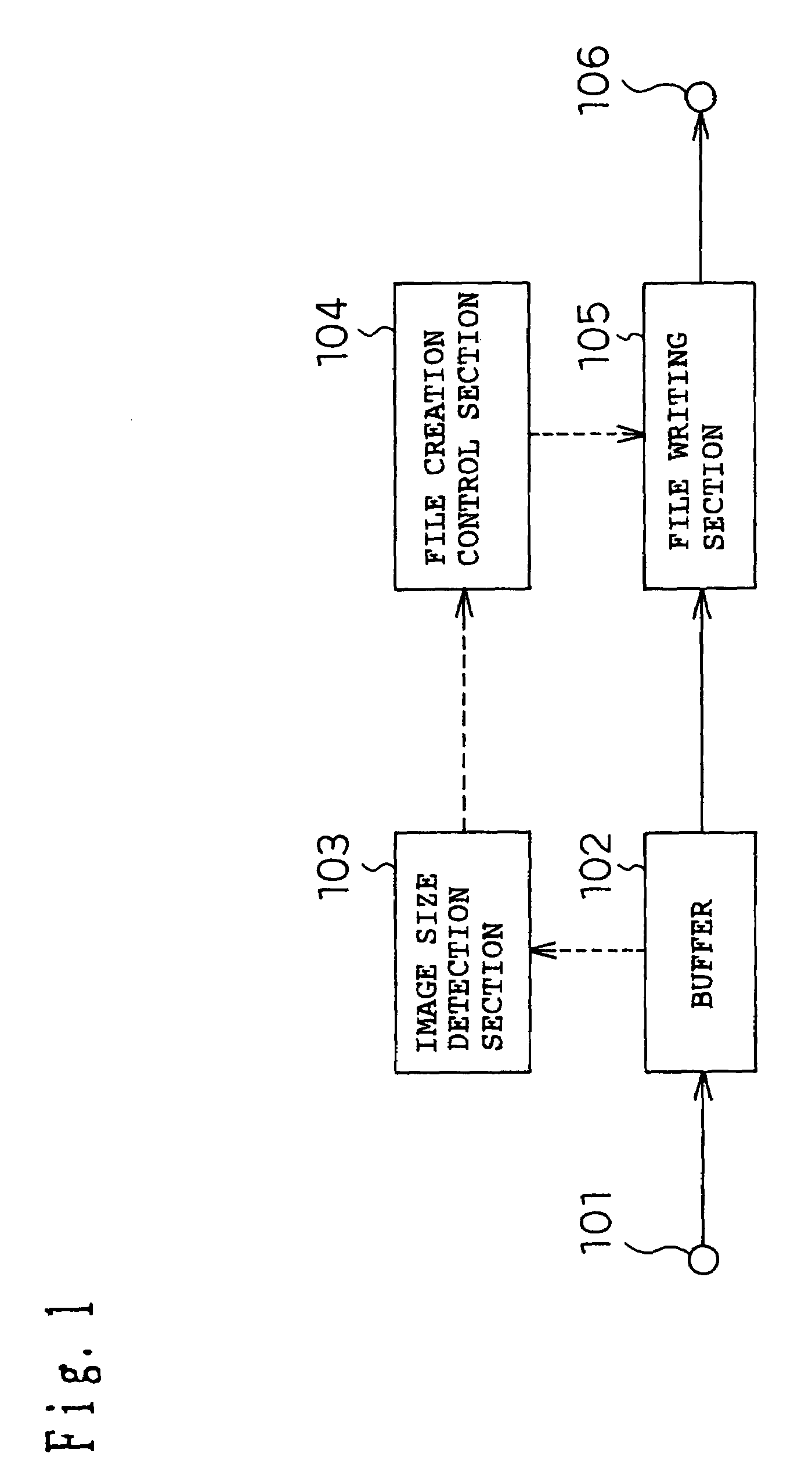
[0063]FIG. 1 illustrates a configuration of a data capture apparatus according to a first embodiment of the present invention. In FIG. 1, reference numeral 101 denotes an input section; 102, a buffer; 103, an image size detection section; 104, a file creation control section; 105, a file writing section; and 106, an output section.

[0064]Now, the operation of the first embodiment will be described with reference to FIG. 1. In this embodiment, suppose an upper limit of a file size, that is, a total size is 2 GB.

[0065]Animation data inputted from the input section 101 is stored in the buffer 102 in frame units. The animation size detection section 103 detects a frame number (1, 2, . . . , K; K: positive integer) of frame-unit video data stored in the buffer 102 and size of each frame (frame size). The animation size detection section 103 also calculates the total size, which accumulates frame sizes in the frame number order. Analyzing the header section of the DV data format makes it p...

second embodiment

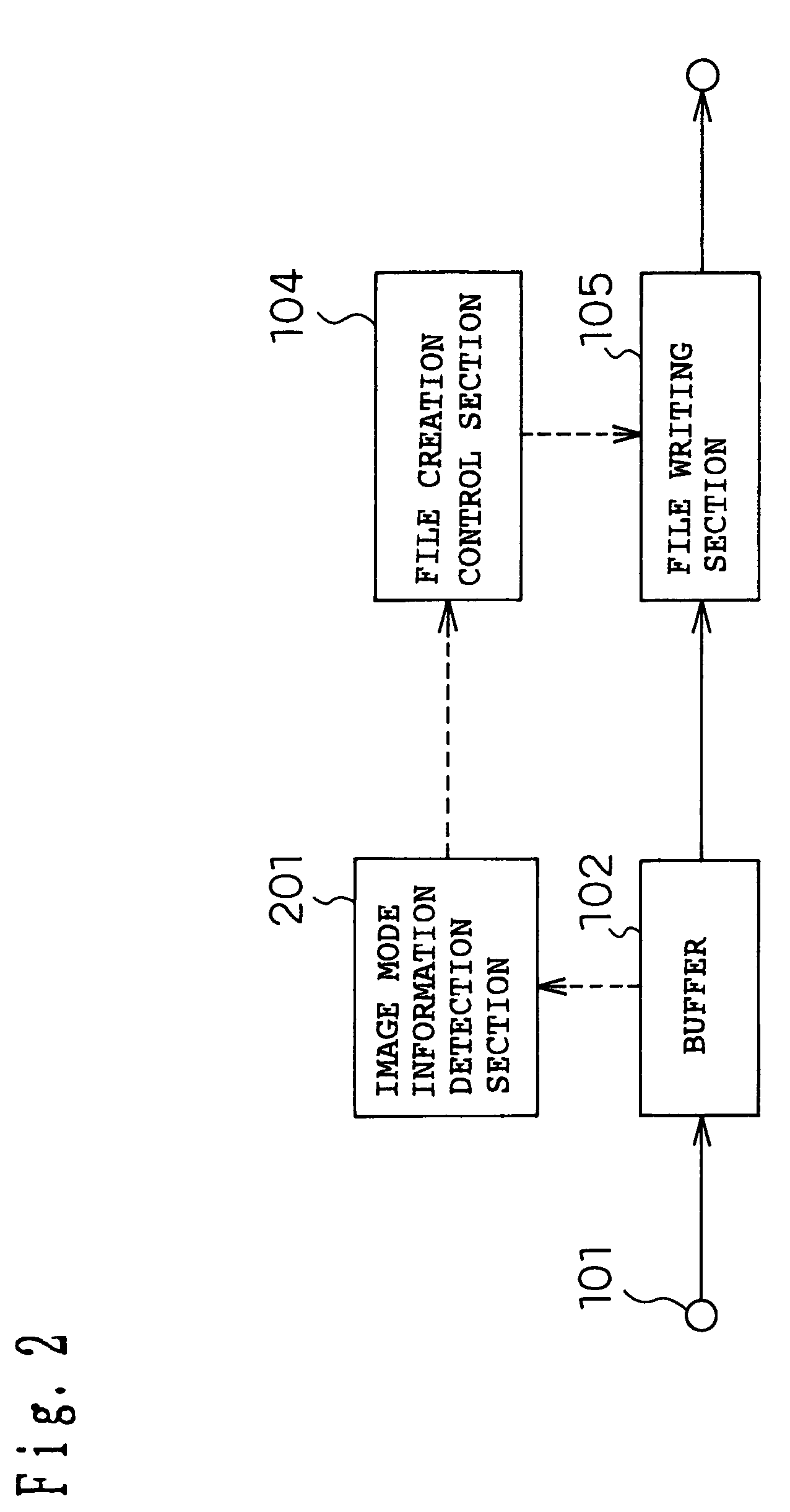
[0077]FIG. 2 illustrates a configuration of a data capture apparatus according to a second embodiment of the present invention. In FIG. 2, reference numeral 201 is an image mode information detection section.

[0078]Now, the operation of the second embodiment will be described with reference to FIG. 2.

[0079]As in the case of the first embodiment, video data input from the input section 101 is stored in the buffer 102 in frame units. An image mode information detection section 201 acquires the image mode information entered. However, in this embodiment, suppose the image mode information at the start of capturing is of an SDTV system. This image mode information is stored, for example, in the header section in a DV format.

[0080]When capturing of animation is started, the file creation control section 104 instructs the file writing section 105 to open file A, which is a file preset for data recording in order to convert the images to a file. The file writing section 105 writes the video...

third embodiment

[0088]FIG. 3 illustrates a configuration of a data capture apparatus according to a third embodiment of the present invention. In FIG. 3, reference numeral 301 denotes a voice mode information detection section.

[0089]The operation of the third embodiment will be described with reference to FIG. 3 below.

[0090]Animation data with voice is input from the input section 101 and stored in the buffer 102 in predetermined units (here, frame units). The voice mode information detection section 301 acquires the voice mode information of the image data entered. However, in this embodiment, suppose the voice mode information at the start of capturing has a sampling frequency of 48 kHz.

[0091]When capturing of animation is started, the file creation control section 104 instructs the file writing section 105 to open file A, which is a file preset for data recording in order to convert the animation to a file. The file writing section 105 writes the video data stored in the buffer 102 in file A as ...


PUM

PropertyMeasurementUnit
frequencyaaaaaaaaaa
frequencyaaaaaaaaaa
frequencyaaaaaaaaaa

Abstract

A data recording apparatus that sequentially input: data configured in units that cannot be recorded across different files and records the data in a file having a predetermined volume, has: size detecting unit for deciding when data is sequentially recorded in file, whether next unit of the data to be recorded can be fully recorded in the same file, or not; file creation controlling unit for recording said next data to be recorded in another file or stopping recording if the case where the result of the decision by said size detecting unit shows that recording is not possible; and file writing unit for writing data in a file according to the control from said file creation controlling unit.

Description

BACKGROUND OF THE INVENTION[0001]1. Field of the Invention[0002]The present invention relates to a data recording apparatus that captures data to be continuously processed such as video data or voice data into a computer, converts the data to a file and records it in a recording medium such as a hard disk.[0003]2. Related Art of the Invention[0004]Capturing video data recorded in a video camera, etc. into a computer and converting it in an animation file is called “image capturing.” A typical example of formatting of this image captured animation file is an AVI file handled by the Windows operating system.[0005]With commercialization of the IEEE1394 interface and increasing-capacity of hard disk drives in recent years, it is now possible to handle relatively low-compression rate video data such as DV (Digital Video) as an AVI file.[0006]As a result, it is possible to easily capture a high-quality animation recorded in a DV format into a computer and to edit it by software without de...

Claims


Application Information

Patent Timeline
Patent Type & Authority Patents(United States)
IPC IPC(8): H04N5/93H04N5/91G11B20/00G11B20/10
CPCG11B20/00G11B20/10G11B20/00768G11B20/00086
Inventor ONO, TADASHIJURI, TATSURO
Owner PANASONIC CORP
Learn More