
Simulation method, simulation program, and semiconductor device manufacturing method each employing boundary conditions

a simulation program and semiconductor device technology, applied in stochastic cad, instruments, cad techniques, etc., can solve problems such as failure of semiconductor devices, difficult selection of proper boundary conditions for simulation, and unintended simulation results

Inactive Publication Date: 2007-01-09
KK TOSHIBA
View PDF24 Cites 4 Cited by
  • Summary
  • Abstract
  • Description
  • Claims
  • Application Information

AI Technical Summary

Benefits of technology

The present invention provides a method for simulating a semiconductor device design using boundary conditions set for a calculation area. The method includes determining the influence of boundary conditions on the inside of the calculation area, displaying the influence of boundary conditions for the user to review, and allowing the user to change the boundary conditions if desired. The method also includes carrying out the simulation and outputting the results for further analysis. The technical effect of this invention is to improve the accuracy and efficiency of semiconductor device design simulation by incorporating boundary conditions and their influence on the calculation area.

Problems solved by technology

When relatively simple boundary conditions such as mirror, fixed, or periodic boundary conditions are improper for a given simulation, it is difficult to choose proper boundary conditions for the simulation.
If improper boundary conditions are set for the simulation, an unintended simulation result will be obtained.
If the unintended simulation result is passed unnoticed to design a semiconductor device, it leads to a failure of the semiconductor device.

Method used


Image

  • Simulation method, simulation program, and semiconductor device manufacturing method each employing boundary conditions
  • Simulation method, simulation program, and semiconductor device manufacturing method each employing boundary conditions
  • Simulation method, simulation program, and semiconductor device manufacturing method each employing boundary conditions

Examples


Embodiment Construction

[0019]Various embodiments of the present invention will be described with reference to the accompanying drawings. It is to be noted that the same or similar reference numerals are applied to the same or similar parts and elements throughout the drawings, and the description of the same or similar parts and elements will be omitted or simplified.

[0020]The present invention is applicable to, for example, process simulations and device simulations carried out to design a semiconductor device. A term “simulation” includes process simulation and device simulation in this specification. Also an apparatus used to carry out the process simulations and device simulations is called a simulation system in this specification.

[0021](Simulation System)

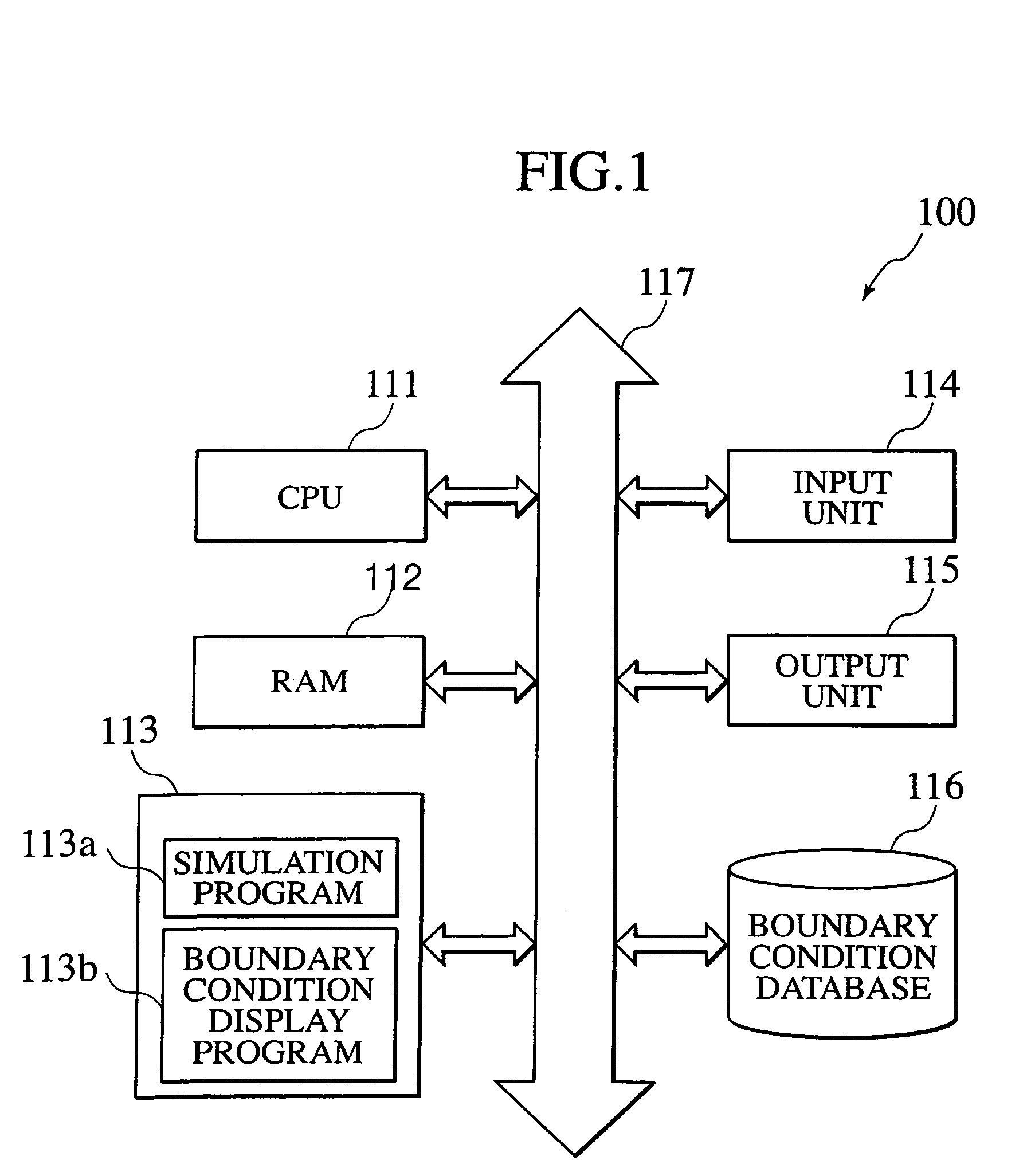
[0022]FIG. 1 is a block diagram showing a simulation system 100 according to an embodiment of the present invention. The simulation system 100 has a CPU 111, a RAM 112, a memory 113, an input unit 114, an output unit 115, a boundary condition databa...


PUM


Abstract

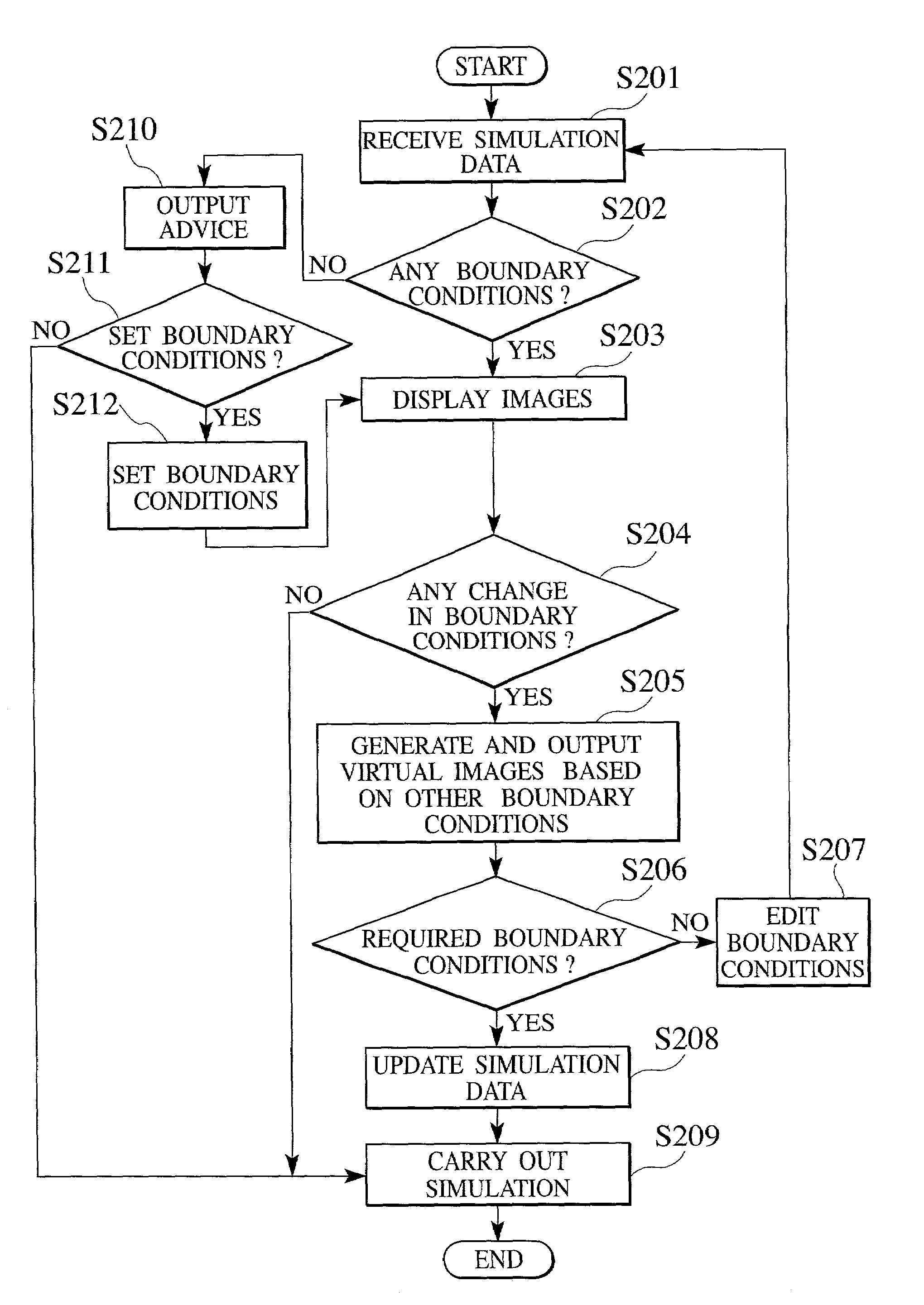
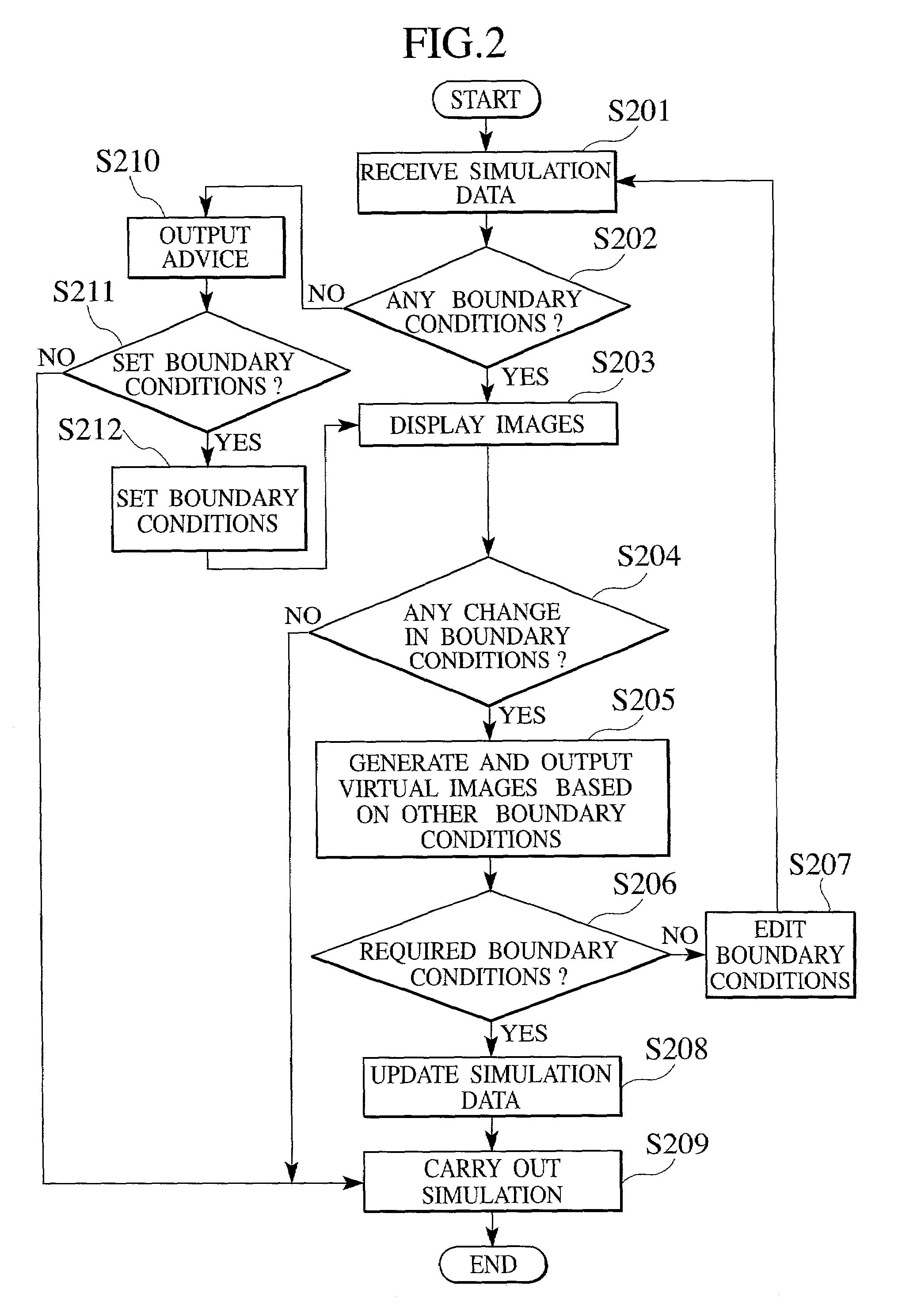
An aspect of the present invention provides a method of carrying out a simulation with simulation data, including, determining whether or not the simulation data includes boundary conditions set for a boundary of a calculation area set for the simulation, computing the influence of the boundary conditions on the inside of the calculation area if the simulation data includes the boundary conditions, displaying the influence of the boundary conditions on the inside of the calculation area, prompting to enter an instruction whether or not the boundary conditions are changed, and if an instruction to make no change in the boundary conditions is entered, carrying out the simulation with the simulation data.

Description

CROSS REFERENCE TO RELATED APPLICATIONS[0001]This application is based upon and claims benefit of priority from the prior Japanese Patent Application No. P2000-402778 filed on Dec. 28, 2000, the entire contents of which are incorporated by reference herein.BACKGROUND OF THE INVENTION[0002]1. Field of the Invention[0003]The present invention relates to a simulation method, a simulation program, and a semiconductor device manufacturing method. In particular, the present invention relates to a technique of simulating semiconductor device processes employing to boundary conditions.[0004]2. Description of the Related Art[0005]A simulation of the manufacturing processes or electric characteristics of a semiconductor device is usually restricted by various conditions such as a computation time and a computer memory capacity. To comply with the restrictions, the simulation is carried out by setting a finite calculation area. Especially, a simulation involving three-dimensional calculations ...

Claims


Application Information

Patent Timeline
Patent Type & Authority Patents(United States)
IPC IPC(8): G06F17/50H01L21/00H01L29/00
CPCG06F17/5018G06F2217/10G06F30/23G06F2111/08
Inventor ITO, SANAEAMAKAWA, HIROTAKA
Owner KK TOSHIBA
Learn More