Card connection adaptor

a card connection and adapter technology, applied in the direction of conveying record carriers, instruments, mechanical means, etc., can solve the problems of inability to directly fit cards into the pc card slot of notebooks, drawbacks of mechanical and electrical viewpoints, and the disconnect of small-size cards, so as to enhance visibility and enhance visibility.

Inactive Publication Date: 2007-01-09
JST MFG CO LTD
View PDF36 Cites 38 Cited by
  • Summary
  • Abstract
  • Description
  • Claims
  • Application Information

AI Technical Summary

Benefits of technology

[0061]In this case, the card visual mechanism may include a window extending through the rear face of the housing to the card retaining space. In this arrangement, at least the periphery of the window in the rear face of the housing is preferably imparted with a color which is distinguishable from the color of the card. Further, the visibility may be enhanced by imparting the housing per se with a color different from the color of the card or by imparting a portion of the card opposed to the window with a color different from the color of the rear face of the housing. The visibility may further be enhanced by fitting a lens in the window.

Problems solved by technology

Since the smaller-size information systems do not always have sufficient data processing power, it is often necessary to load image data picked up by a digital camera into a notebook PC or to transfer data between an electronic organizer and a notebook PC.
However, when data retained in the small-size information system are to be loaded into the notebook PC via a CF card or a small-size memory card, for example, such a card cannot directly be fitted in the PC card slot of the notebook PC because the PC card slot is designed in compliance with the PC Card Standard.
However, this arrangement has drawbacks from mechanical and electrical viewpoints.
Hence, there is a possibility that the small-size card is disconnected from the card connection adaptor by some external force.
If the small-size card is disconnected during data transfer between an information system and the small-size card, the data transfer is of course failed, and destruction of date or destruction of elements inside the small-size card may result from erroneous signal input.
This is particularly problematic in the case of a card which is designed to lead signal input / output interconnections from the small-size card (e.g., GSM card).
Further, it is difficult to provide a lock holder in the card connection adaptor for assuredly holding the small-size card, whereas it is easy to provide a holder mechanism in a PC card slot for holding a card inserted therein.
In such a case, a great external force is exerted onto the connector of the PC card slot, so that the connector may be damaged.
In addition, there is a possibility that the small-size card is inserted into or withdrawn from the card connection adaptor fitted in a PC card slot when the information system is energized.
It is, therefore, extremely difficult to design the card connection adaptor which can offer a guarantee against the active insertion and withdrawal.

Method used


Image

  • Card connection adaptor
  • Card connection adaptor
  • Card connection adaptor

Examples


second embodiment

[0120]FIG. 10 is a plan view illustrating the construction of a card connector used for connection to the MultiMedia card in the present invention. For explanation of this embodiment, reference is made again to FIGS. 1 through 5, 8 and 9.

[0121]The card connector 50 used in this embodiment has terminals 51 of the same number as that of the terminals 111 of the card 100 (i.e., seven terminals 51). Among these terminals, a terminal 51a through which a source voltage is supplied to the card 100 serves for double purpose as a switch terminal. More specifically, the terminal 51a has the same construction as the switch terminal 22b in the first embodiment previously described, as shown in FIG. 11, and a contact 52 (of the same construction as the contact 28 in the first embodiment) connected to the light emitting diode 27 is provided on the wiring board 40.

[0122]When the card 100 is inserted into the card retaining space 2, the terminals 51 are resiliently deformed to be brought into press...

third embodiment

[0124]FIG. 12 is a block diagram for explaining the present invention. For the explanation of this embodiment, reference is made again to FIGS. 1 through 5 and 8 through 11. The third embodiment employs a card connector having substantially the same construction as the card connector 50 shown in FIG. 10, but there is no need to provide the terminal serving for double purpose as the switch terminal. The terminals 51 to be brought into one-to-one correspondence with the terminals 111 may be arranged so that connection only to the corresponding terminals 111 can be established. Accordingly, there is no need to provide the contact 52 on the wiring board 40.

[0125]In the third embodiment, the control IC 41 is employed for controlling the power supply to the light emitting diode 27. The control IC 41 boosts the source voltage supplied from the information system 300 via the slot connector 21 by means of a booster circuit 41a, and supplies the voltage to the card 100. When the card 100 is i...

fourth embodiment

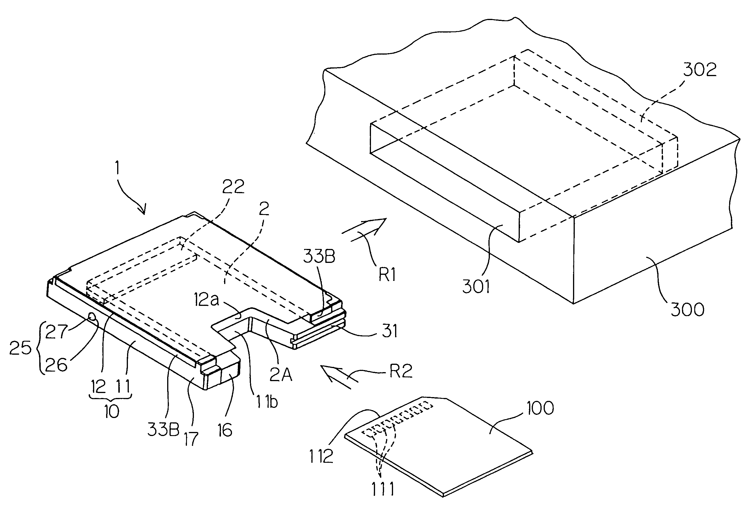
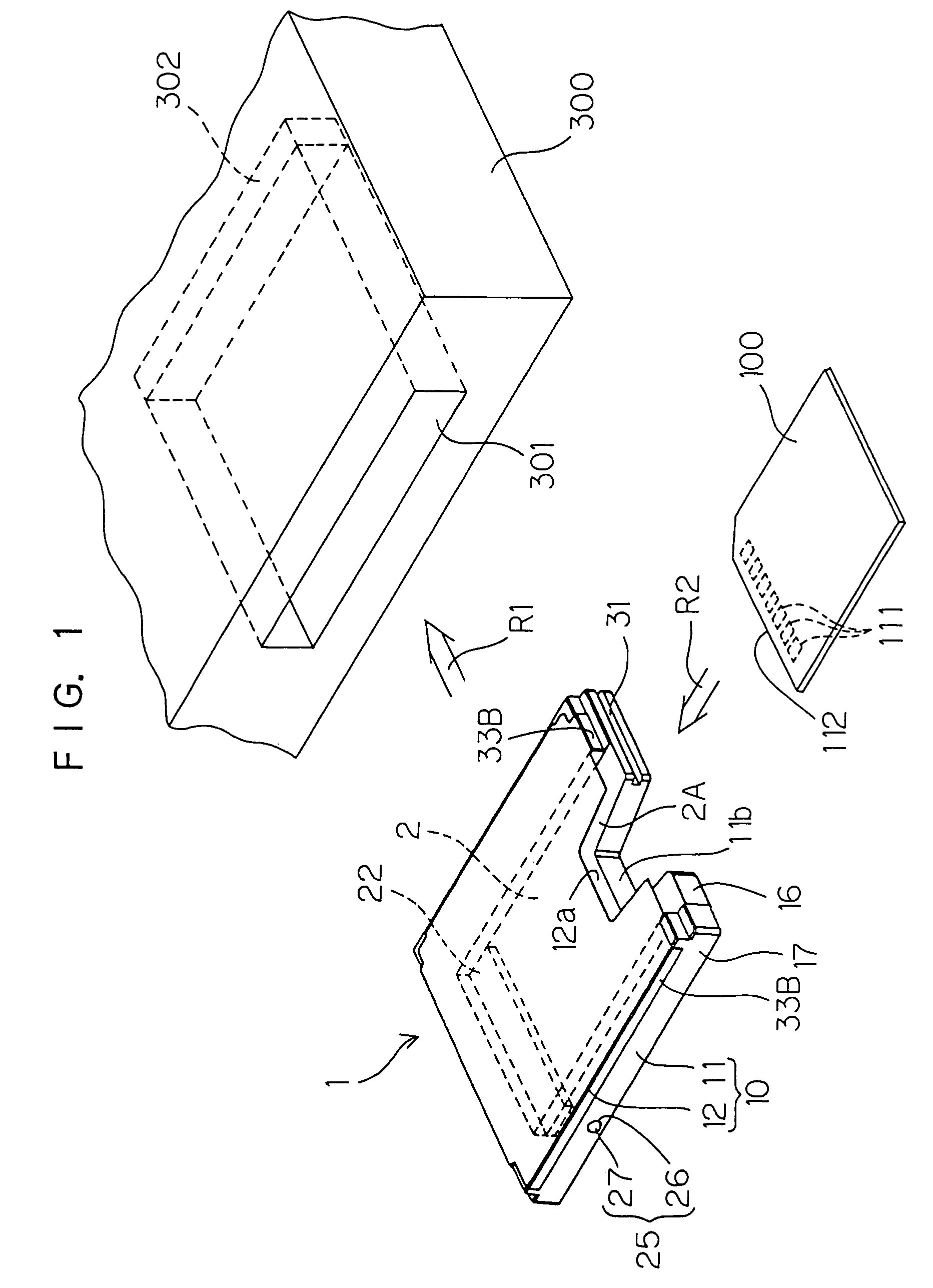
[0129]FIG. 13 is a plan view illustrating the internal construction of a card connection adaptor according to the present invention. FIG. 14 is a sectional view taken along a section line XIV—XIV in FIG. 13. In FIGS. 13 and 14, like components corresponding to those shown in FIGS. 1 through 9 are denoted by like reference characters.

[0130]A difference between the card connection adaptor 1A (hereinafter referred to simply as “adaptor 1A”) according to the fourth embodiment and the adaptor 1 according to the first embodiment resides in the construction of the indication mechanism for providing an indication of the presence or absence of the card 100 in the adaptor on the rear face 17 of the housing 10 (frame 11).

[0131]More specifically, the indication mechanism 70 of the adaptor 1A of this embodiment includes a flat spring 71 attached to the press frame 11B, and a window 72 formed in the rear face 17 of the housing 10 (frame 11). As shown in a perspective view of FIG. 15, the flat spr...


PUM


Abstract

A card connection adaptor is provided which is used for connecting, to a connector of a card slot compliant with a first standard, a card compliant with a second standard. The adaptor includes: a first connector compliant with the first standard and adapted to be electrically connected to the connector of the card slot; a second connector compliant with the second standard; and signal conversion circuitry for performing signal conversion between a first-standard-compliant signal and a second-standard-compliant signal. A card retaining space for retaining the second-standard-compliant card inserted therein is formed in a housing which holds the first connector, the second connector and the signal conversion circuit. The card retaining space has a card insertion port which opens generally perpendicularly to an insertion direction in which the card connection adaptor is inserted into the card slot.

Description

[0001]This application is a division of Ser. No. 09 / 264,564 filed Mar. 8, 1999, now U.S. Pat. No. 6,408,352.BACKGROUND OF THE INVENTION[0002]1. Field of the Invention[0003]The present invention relates to a card connection adaptor for connecting an IC card such as a memory card or a functional extension card to an information system such as a personal computer, or a portable information system represented by a PDA (personal digital assistant), a digital still camera and a digital video camera.[0004]2. Description of Related Art[0005]Recent notebook PCs (personal computers) are generally equipped with PC card slots. Functional extension of such a notebook PC can be achieved by inserting a PC card into the PC card slot. Exemplary PC cards include flash memory cards, modem cards and SCSI cards.[0006]The PC cards are designed in compliance with the PC Card Standard, and classified into three types which have thicknesses of 3.3 mm (Type I), 5.0 mm (Type II) and 10.5 mm (Type III), respec...

Claims


Application Information

Patent Timeline
Patent Type & Authority Patents(United States)
IPC IPC(8): G06F3/00G06F13/12G06F3/01G06F1/18G06K13/077G06K17/00G06K19/077
CPCG06K19/077G06K19/07741Y10S439/945G06K7/04
Inventor HOSAKA, TAIJIYASUFUKU, KAORI
Owner JST MFG CO LTD
Why Eureka
Try Eureka