
Concrete formwork wall serving also as reinforcement

Inactive Publication Date: 2007-01-16
COFFOR INT EXPLORACAO DE PATENTES
View PDF28 Cites 27 Cited by
  • Summary
  • Abstract
  • Description
  • Claims
  • Application Information

AI Technical Summary

Benefits of technology

[0011]One of the objectives of the invention is to further increase the strength of concrete walls obtained with the aforementioned kind of formwork, especially by an internal reinforcement, in a simple way and eliminating or reducing the use of separated reinforcement elements to be installed on the construction site.
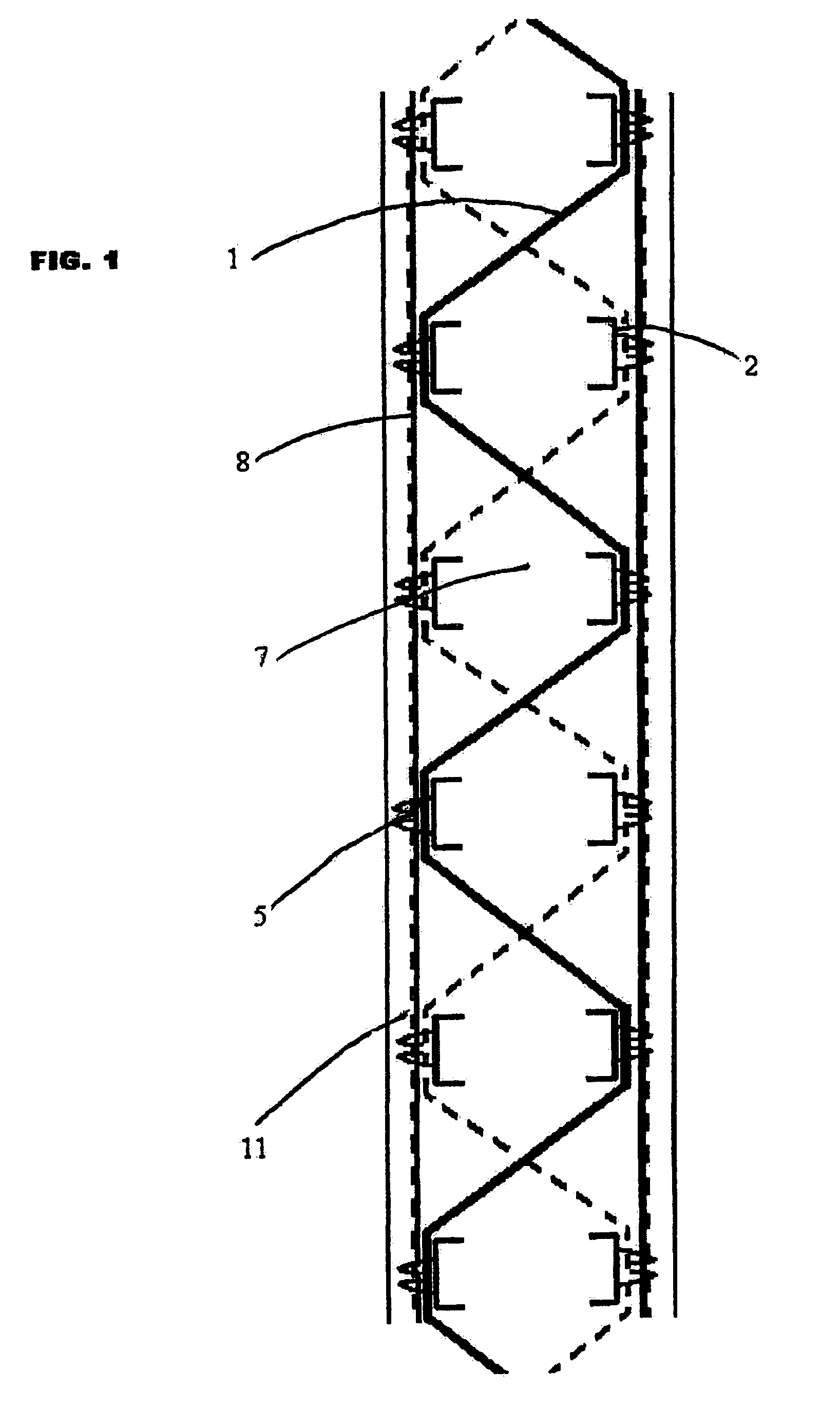
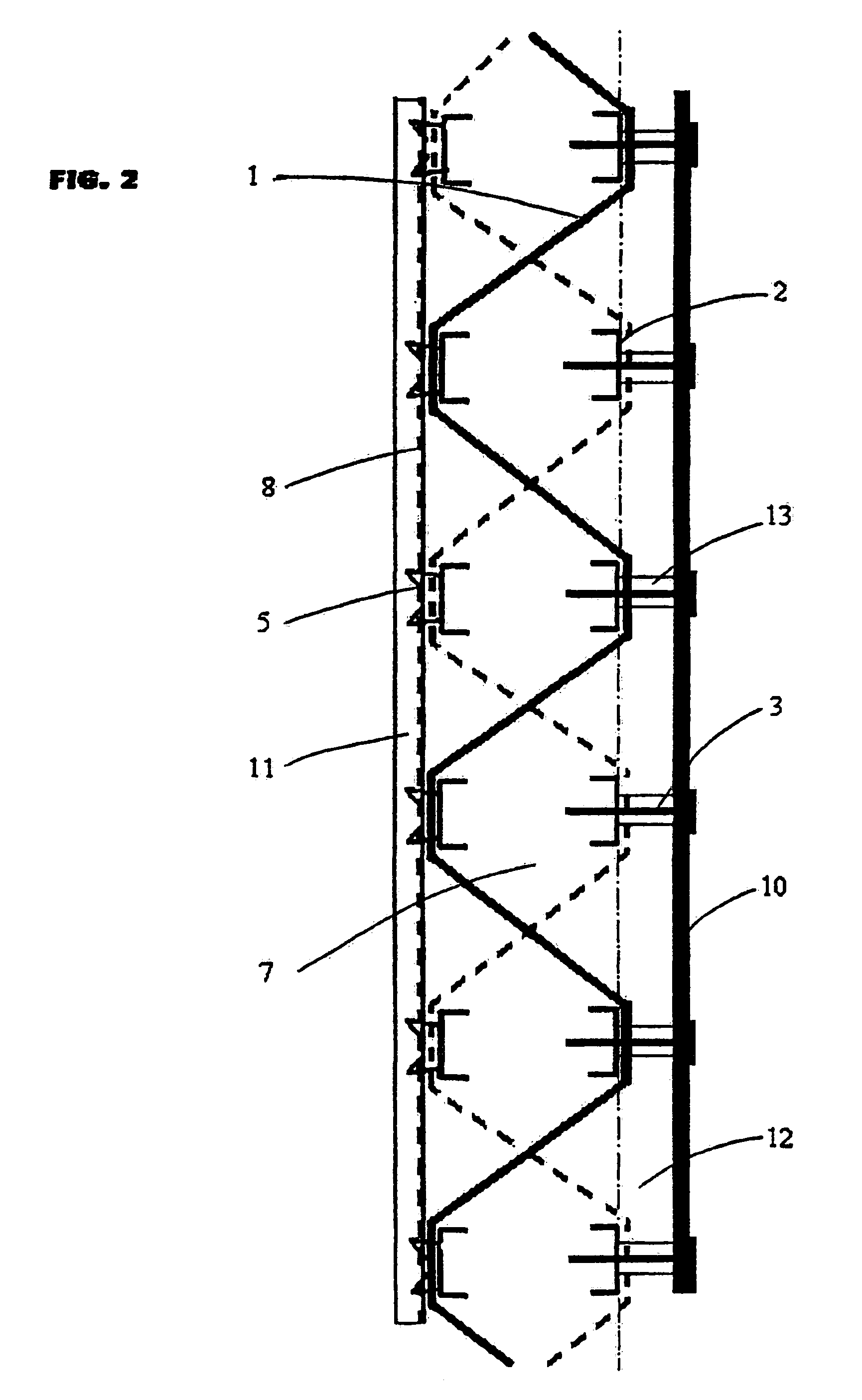
[0012]Another object of the invention is a wall made of concrete or similar materials built from an unfolded formwork integrated in the wall and including two formwork walls placed face to face and connected by articulated connecting elements to the formwork walls by means of stiffeners attached to the formwork walls, the interval between these unfolded formwork walls being filled by a filler such as concrete. The articulated connecting elements of this permanent formwork, after having served at first to facilitate the transport and the setting of the formwork, constitute, once the formwork is installed, an element of reinforcement that increases the strength of the wall.
[0014]Furthermore, unlike the walls according to WO 97 / 31165 and FR 2 675 181, the formwork walls (or at least one of them) do not constitute the skin of the wall, but are submerged within the wall by said casing, in such a way to constitute also an internal reinforcement of the wall, which considerably increases the reinforcement or “hoop” effect.
[0015]The casing of these three elements (stiffeners, articulated connections and formwork walls) reduces or eliminates the need for inserting separated stiffeners on the construction site before pouring the concrete.
[0017]The steel parts of the formwork—stiffeners, articulated connecting elements and expanded metal of the walls—are thus coated with a concrete / mortar thickness preferably of at least 2.5 cm being part of the wall. This will allow then the inclusion of these elements in the calculation of the wall strength and, furthermore, the reduction, i.e. suppression, in some cases, the steel quantities to be added in the formwork. On the other hand, the casing of these parts will allow the use of a non-galvanized steel in the manufacture of the formwork, being in this way less expensive.
[0027]compression forces oriented generally in a parallel direction to the external faces of said wall so as to create a skin having a hoop effect whose efficiency is increased thanks to their form and their particular arrangement assuring the distribution of the forces within the above described wall, especially in that the connection elements and the stiffeners constitute a reinforcement submerged inside the wall.

Problems solved by technology

The crossbars submerged in the concrete, which no longer have any function, can be left in place or withdrawn and do not contribute to in the strength of the wall, but on the contrary, make it more fragile.
However, with this known device, it seems necessary or desirable to include an internal reinforcement, which is difficult to make while the formwork is being manufactured.
This operation is expensive and time consuming.

Method used


Image

  • Concrete formwork wall serving also as reinforcement
  • Concrete formwork wall serving also as reinforcement
  • Concrete formwork wall serving also as reinforcement

Examples


third embodiment

[0046]the invention is disclosed in FIG. 3. The wall is similar to that of FIG. 2, but includes two perforated walls 8,8′ and, furthermore, an insulating panel 4, for example of polyurethane or of rock wool or other insulating or fire-proof material, adjacent to the wall 8′ which forms the external face of the wall. On this side, the connecting device 1 is articulatably joined to the stiffeners 2 attached to the panel 8′ but separated from this one by means of holds 13 attached by screws 3, or other hooking means, which extend beyond the stiffeners 2.

first embodiment

[0047]On the wall 8′ side, the concrete 7, or other filler, forms a thickness 12 between the internal face of the insulating panel 4 (which has a formwork panel effect) and the stiffeners 2 with the corresponding parts of the z-shaped connectors. the length of the holds 3 is defined in that a space between the insulating panel 4 and the stiffeners 2 forms a thermal decoupling. According to another embodiment, the holds 3 are defined in such a way that the insulating panel 4 is held on the stiffeners 2.

[0048]This embodiment has the supplementary advantage that the insulating panel 4 is included in the folded formwork, which allows a valuable time gain during the building, because once the concrete is poured, it will no longer be necessary to come back and add the insulation. As for the previous embodiment, the stiffeners 2 and the connecting device 1 forms reinforcement submerged by a thicknesses 11, 12, thus situated within the wall.

[0049]The walls illustrated in FIGS. 1, 2 and 3 a...


PUM


Abstract

Wall made of concrete or similar materials built from an unfold formwork integrated in the wall and including two formwork walls (8,8′,10) placed face to face and connected by connecting elements (1) articulated to the formwork walls by stiffeners (2) attached to the formwork walls. The interval between these formwork walls after being unfolded is filled with a filler (7) such as concrete.At least one of the formwork walls includes a casing (11,12) of concrete, mortar or similar, surcharged in relation to the stiffeners (2) and to the articulated connecting elements (1). This casing (11,12) is placed outside and / or inside the formwork wall, the stiffeners (2) and the articulated connecting elements (1) and the formwork wall 8 when it is coated forming an inner reinforcement of the wall submerged in the wall and covered by said casing.The use of separated stiffeners, which must be inserted before pouring the concrete, is thus avoided or highly reduced.

Description

TECHNICAL FIELD[0001]The invention refers to a wall made of concrete or similar materials built from a permanent unfolded formwork integrated in the wall and including two formwork walls placed face to face and connected by articulated connecting elements to the formwork walls by means of stiffeners attached to the formwork walls, the space between these formwork walls after being unfolded being filled in with a filler such as concrete.[0002]The invention also concerns a method for building such a wall as well as a specially adapted formwork / reinforcement for the construction of this wall.BACKGROUND OF THE INVENTION[0003]To raise concrete walls, formworks that define a volume in which concrete is poured are typically used. Usually, these formworks comprise: two walls placed face to face defining between them an interval where concrete is introduced, and connecting devices holding the walls with the required spacing. For example, connecting devices can be crossbars, whose ends suppor...

Claims


Application Information

Patent Timeline
IPC IPC(8): E04B1/00E04B1/74E04B1/16E04B2/84E04B2/86
CPCE04B2/8635E04B2/8658E04B2002/8694E04B2/86
Inventor MESSIQUA, PIERRE
Owner COFFOR INT EXPLORACAO DE PATENTES
Learn More