Soft tissue securing anchor

a soft tissue and anchoring technology, applied in the field of surgical devices, can solve the problems of inefficient use of patient's operative time as well as surgeon's time, less than optimal use of many operative procedures, and inability to rethread a suture through the suture, so as to reduce the cost of operative time and time, and efficiently attach soft tissue.

Inactive Publication Date: 2007-01-16
VITE TECH
View PDF12 Cites 43 Cited by
  • Summary
  • Abstract
  • Description
  • Claims
  • Application Information

AI Technical Summary

Benefits of technology

[0010]In a first aspect of the present invention, the anchor holes are inclined so that with the soft tissue securing anchor seated in the bone, the upper and lower apertures of each anchor hole are accessible to attach separate sutures to each of the anchor holes using conventional surgical techniques, i.e. curved needles. Any other variety of surgical needles may also be used. Additionally, free sutures, without attached needles may be threaded through these holes. The inclined anchor holes allow a surgeon to efficiently attach soft tissue to the soft tissue securing anchor using her preferred surgical tools without the necessity of using a multiplicity of specialized tools. Thereby making any given surgery more efficient and cutting down on costly operative time as well as time that the patient is exposed to potentially life-threatening anesthesia. The presence of a plurality of anchor holes in a single soft tissue securing anchor permits a surgeon to secure a plurality of soft tissue points with fewer soft tissue securing anchors than she would have been required using conventional anchors that only accommodate a single suture.
[0011]In another aspect of the present invention, the lower surface of the anchor head is angled relative to the long axis of the soft tissue securing anchor. The angle chosen is dictated by the surgeon's choice of needle and suture for a particular application. The angle of the lower surface of the anchor head combined with the angle of the anchor holes allows the surgeon to efficiently attach one or more sutures to a single soft tissue securing anchor. This minimizes the amount of foreign bodies that are surgically placed in a patient's body. Foreign body tissue reaction may lead to an increased rate of infection and, therefore, with the present invention, the patient would benefit with a lowered rate of foreign body tissue reaction. Additionally, since the suture to anchor body interface is very important with respect to operative stability, the possibility of now securing multiple soft tissue points to one anchor via the present invention means that if a single suture were to break, the operative approximation of soft tissue to bone or soft tissue to soft tissue would not be lost, as it is with the breaking of a suture attached to a conventional anchor.
[0012]In a further aspect of the present invention, each aperture of each anchor hole is chamfered to accommodate surgical needles. The chamfered aperture simplifies the surgeon's task of introducing the surgical needle into the anchor hole by widening the entry and exit apertures, and thus funneling the surgical needle point to the center of the anchor hole. The chamfer also lessens the angle of approximation the surgeon must achieve with a surgical needle to successfully pass the surgical needle and suture through the anchor hole. The chamfered areas, from the anchor hole to the outside edge, shall be polished or somehow smoothed to remove sharp edges and rough areas which may cause friction and abrasion of the tissue-approximating suture or the soft tissue itself. The chamfered aperture also minimizes acute edges in contact with the suture to minimize abrading of the suture thus allowing the liberal use of sliding knots on sutures passing through the present invention.

Problems solved by technology

The conventional devices have some disadvantages which render them less than optimal for use in many operative procedures.
Once a conventional anchor is secured in place, a surgeon is generally not able to rethread a suture through the suture-securing hole if the suture should break or otherwise come louse.
This leads to the inefficient use of the patient's operative time as well as the surgeon's time.
First, the surgeon must gather the special tools necessary to use the conventional anchor.
Second, the surgeon must thread the suture provided with the conventional anchor using a specialized threading tool.
Fourth, the surgeon must attach a conventional anchor to a special insertion tool.

Method used


Image

  • Soft tissue securing anchor
  • Soft tissue securing anchor
  • Soft tissue securing anchor

Examples


Embodiment Construction

)

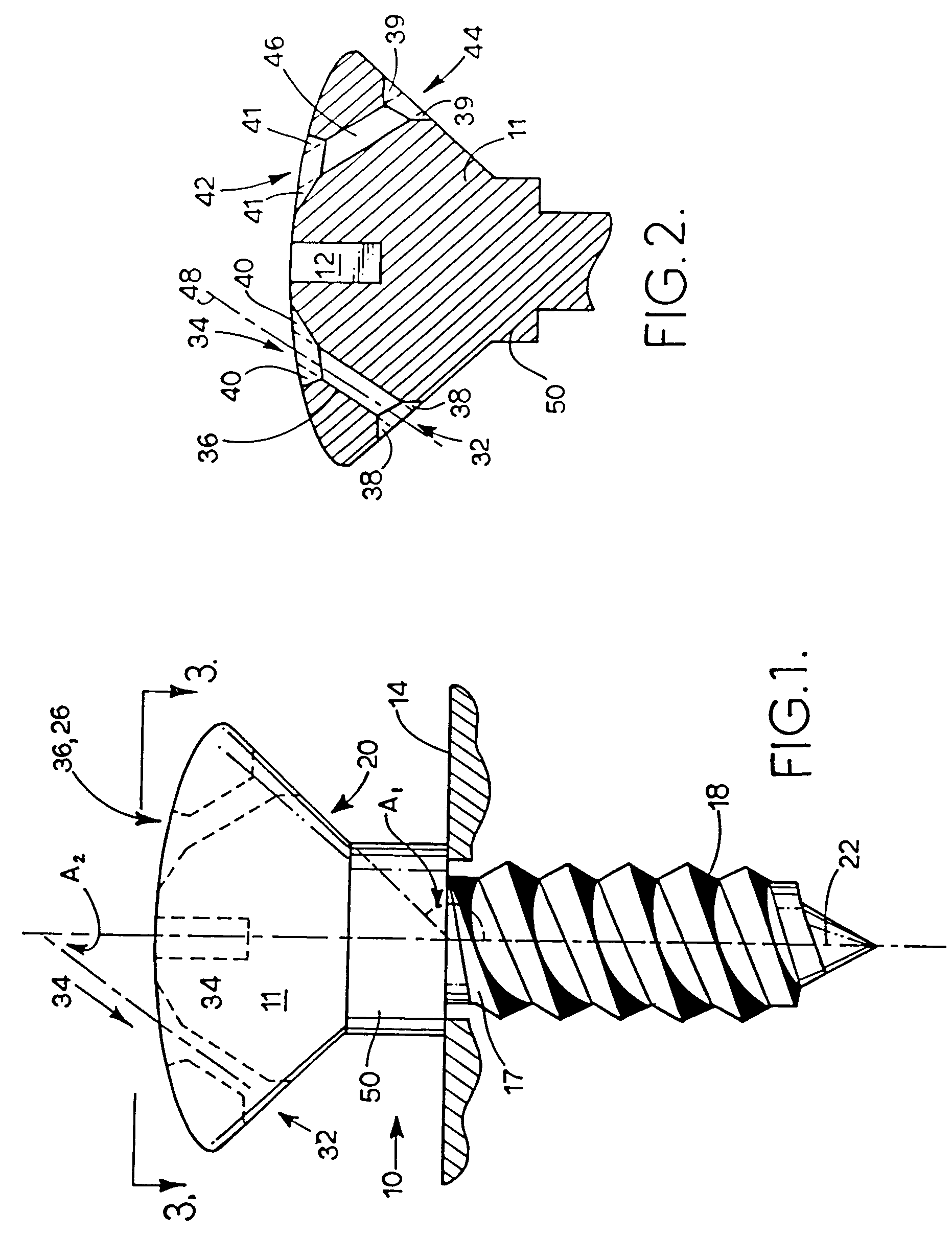
[0026]Referring to FIG. 1, soft tissue securing anchor 10 includes head 11 and securing end 18. Securing end 18 may include any conventional means of securing a suture anchor into bone such as threads, barbs, fingers, toggle or molly bolts, and rivets. Suture anchor 10 may be secured into bone by any conventional means such as the application of torque or press-fit. The currently preferred embodiment of the present invention is a threaded, self tapping screw having a shoulder 50 which delineates head 11 from shank 17. Shoulder 50 provides a visual and physical indication to the surgeon to stop inserting soft tissue securing anchor 10 when shoulder 50 contacts bone 14. The size of shoulder 50 and the shape of head 11 are selected to permit access by surgical needle to both upper and lower apertures such as upper aperture 34 and lower aperture 32. Raising lower aperture 32 above bone 14 permits easy access to lower aperture 32. Head 11 may include a means for accommodating a drive to...


PUM


Abstract

A surgical anchor is provided with one or more anchor holes distributed around the head of the anchor. Each anchor hole is inclined to allow attachment of one or more sutures to the anchor either before, during or after the anchor is seated in a bone. The upper and lower apertures of each anchor hole are chamfered, and the chamfered areas from the anchor hole to the outside edge shall be polished or somehow smoothed to remove sharp edges and rough areas which may cause friction and abrasion to soft tissue or suture material. The lower surface of the anchor head may be angled to further simplify the task of feeding a surgical needle through the anchor hole after the anchor is seated into the bone.

Description

RELATED APPLICATIONS[0001]This invention claims priority of copending U.S. provisional patent application Ser. No. 60 / 048,284. This is a divisional application of Ser. No. 09 / 747,991 filed on Dec. 27, 2000 now U.S. Pat. No. 6,648,892 which is a continuation of Ser. No. 09 / 089,231, filed on Jun. 2, 1998, now U.S. Pat. No. 6,168,598 which claimed the just-mentioned priority.BACKGROUND OF THE INVENTION[0002]1. Field of the Invention[0003]The present invention relates generally to the field of surgical devices. In particular, this invention relates to anchors for attaching soft tissue to bone, and or to other soft tissue.[0004]2. Background of the Invention[0005]There are a number of conventional devices currently being marketed as anchors for securing soft tissue to bone. These devices have found application in surgical repair procedures throughout the human body. The conventional devices have some disadvantages which render them less than optimal for use in many operative procedures.[...

Claims


Application Information

Patent Timeline
Patent Type & Authority Patents(United States)
IPC IPC(8): A61B17/56A61B17/04
CPCA61B17/0401A61B2017/0414A61B2017/044Y10S606/91Y10S606/907Y10S606/908A61B2017/0459
Inventor MARTELLO, JEANNETTE
Owner VITE TECH
Why Eureka
Try Eureka