Diode-based light sensors and methods

a technology of light sensor and diode, applied in the direction of optical radiation measurement, lighting and heating apparatus, instruments, etc., can solve the problems of low illumination, poor assumption, and full dimming of artificial lights

Inactive Publication Date: 2007-01-16
WATT STOPPER
View PDF63 Cites 114 Cited by
  • Summary
  • Abstract
  • Description
  • Claims
  • Application Information

AI Technical Summary

Problems solved by technology

Also, low illumination affects different people differently.
A problem arises because most conventional photo-transducers capture or detect the entire energy spectrum produced by all light sources.
Unfortunately, this is a poor assumption.
This is problematic because the resultant voltage is derived from both natural and artificial light components which include non-visible energy, while the preset, illumination level is set according to visible light standards, e.g., 40 foot candles.
Consequently, this could result in full dimming of the artificial lights when the incoming daylight provides insufficient illumination for a typical room.
Optical filters, however, are expensive.

Method used


Image

  • Diode-based light sensors and methods
  • Diode-based light sensors and methods
  • Diode-based light sensors and methods

Examples


Embodiment Construction

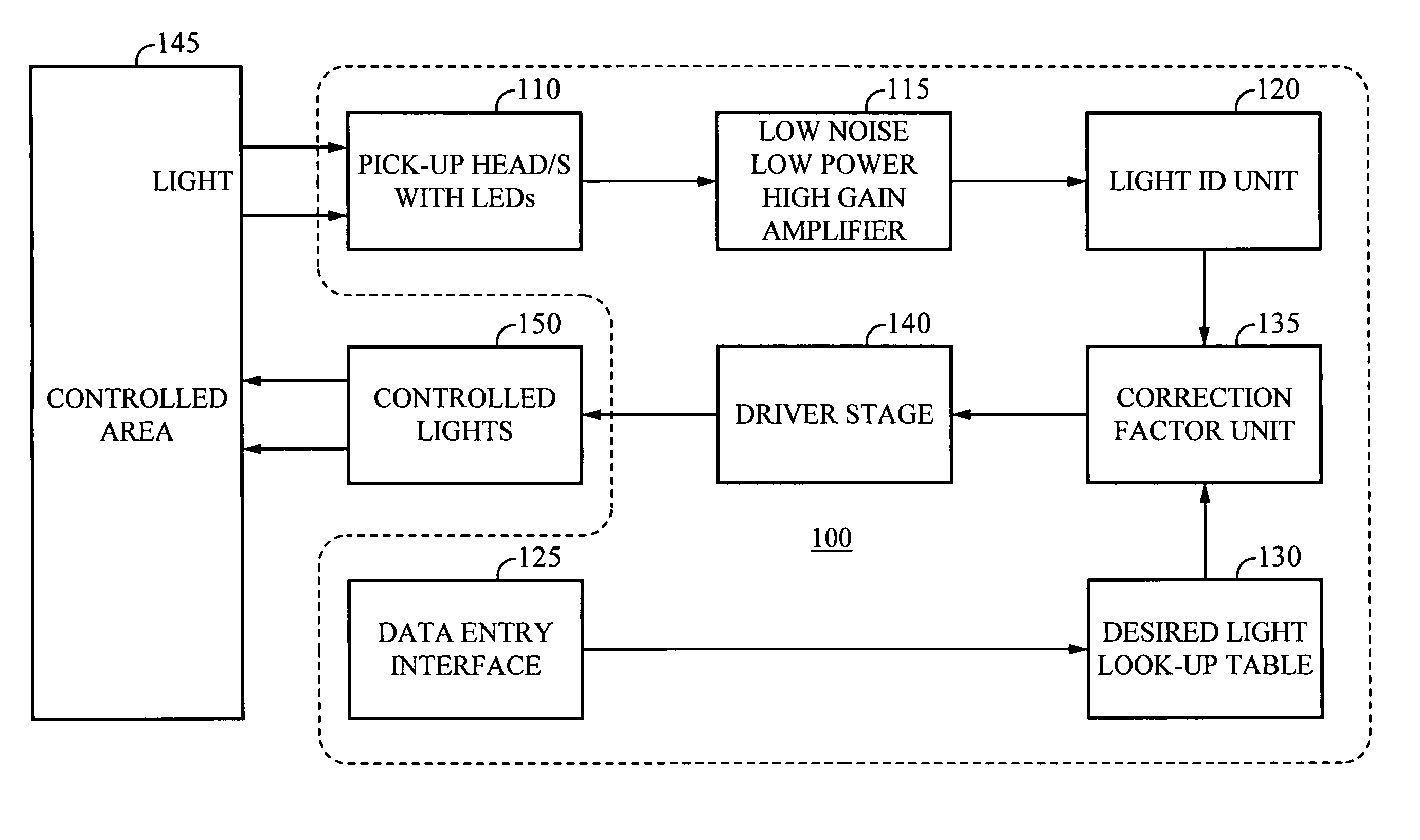
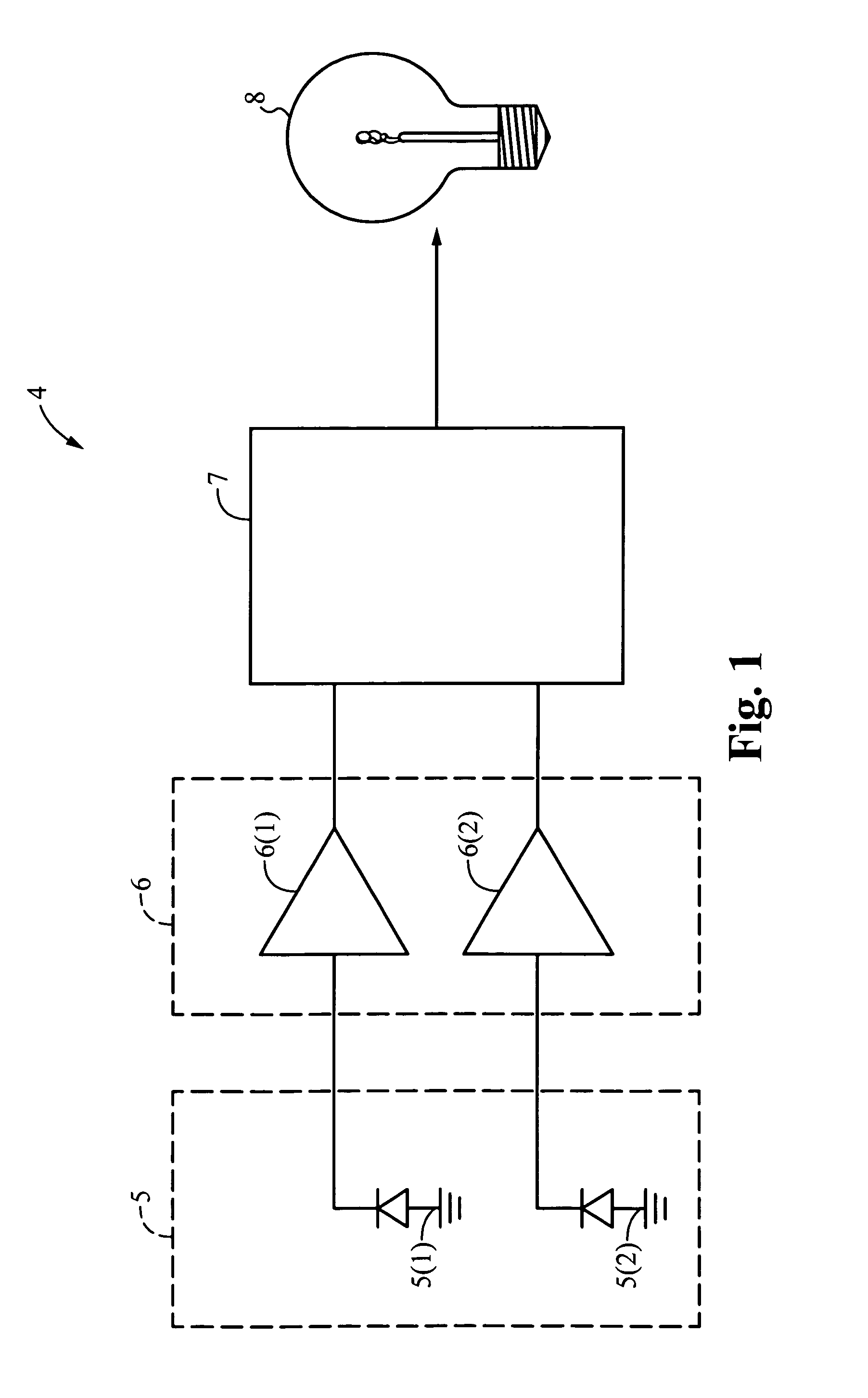
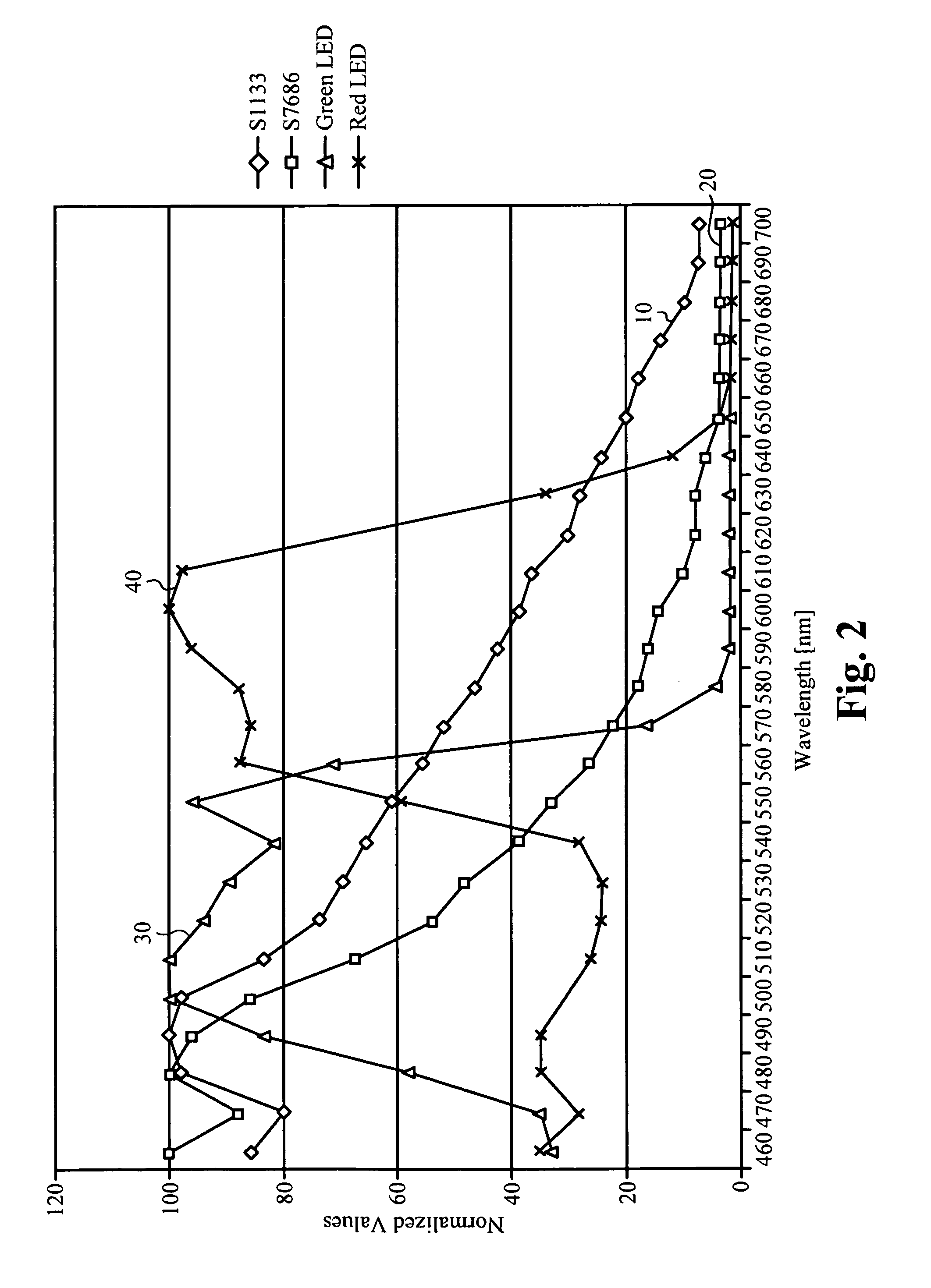
[0019]FIG. 1 shows a simplified high-level block diagram of an illumination management system 4, according to an embodiment of the present invention. Included is a pick-up stage 5, which includes LEDs 5(1) and 5(2). LEDs 5(1) and 5(2) function as pick-up elements for the spectral region of the light in which each of the LEDs would emit light. When LEDs 5(1) and 5(2) are exposed to light, each outputs a signal indicating an intensity of light from its corresponding spectrum. In some embodiments, each LEDs detects light from a unique spectrum. In other embodiments, the spectrums detected by the LEDs can overlap, at least in part. The use of LEDs as light detectors is described in more detail below (description of FIG. 2).

[0020]An amplifier stage 6, which includes amplifiers 6(1) and 6(1), receives, amplifies, and outputs the signals received from pick-up stage 5. A control stage 7 receives amplified signals from amplifier stage 6 and generates a lighting control signal that can be out...


PUM


Abstract

The present invention provides an illumination management system that includes a first LED that outputs a first signal when exposed to a first spectrum of light, the first signal indicating an intensity of light from the first spectrum; a second LED that outputs a second signal when exposed to a second spectrum of light, the second signal indicating an intensity of light from the second spectrum and wherein the second spectrum includes at least some wavelengths that are not in said first spectrum. In some embodiments, more LEDs could be included in the system for associating the presence of light energy from different parts of the light spectrum. Also included is light control circuitry, coupled to the LEDs, configured to generate a lighting control signal that can be output to one or more lights to adjust the lights to a desired light level, wherein the lighting control signal varies in response to said first and second signals.

Description

CROSS-REFERENCES TO RELATED APPLICATIONS[0001]This Application is a continuation application of the U.S. patent application Ser. No. 10 / 431,978, titled “ILLUMINATION MANAGEMENT SYSTEM”, filed May 7, 2003 now U.S. Pat. No. 6,933,486, which is a continuation of U.S. patent application Ser. No. 10 / 045,947, titled “ILLUMINATION MANAGEMENT SYSTEM INCLUDING LEDS FOR DETECTING EXPOSURE TO RADIATION”, filed on Oct. 26, 2001, now U.S. Pat. No. 6,614,013 which claims priority from U.S. patent application Ser. No. 09 / 871,312, titled “LIGHTING CONTROL CIRCUIT”, filed May 30, 2001, now U.S. Pat. No. 6,617,560. The U.S. patent application Ser. No. 10 / 431,978, titled “ILLUMINATION MANAGEMENT SYSTEM”, filed May 7, 2003 and the U.S. Pat. Nos. 6,614,013 and 6,617,560 are all hereby incorporated by reference.BACKGROUND OF THE INVENTION[0002]The present invention relates generally to controlling the output of lights. More particularly, embodiments of the invention relate to a method and apparatus that ...

Claims


Application Information

Patent Timeline
Patent Type & Authority Patents(United States)
IPC IPC(8): G01J1/32F21V9/16H05B39/04H05B41/392
CPCH05B41/3922H05B39/042
Inventor PITIGOI-ARON, RADUFORKE, ULRICHVIALA, ROAR
Owner WATT STOPPER
Why Eureka
Try Eureka