Method and apparatus for improved plasma processing uniformity

a plasma processing and uniformity technology, applied in the direction of electric discharge lamps, electric lighting sources, electric discharge tubes, etc., can solve the problems of increasing the complexity of reactor design, and controlling plasma to obtain uniform etching and deposition, so as to achieve a high degree of process uniformity

Inactive Publication Date: 2007-01-16
TOKYO ELECTRON LTD
View PDF26 Cites 61 Cited by
  • Summary
  • Abstract
  • Description
  • Claims
  • Application Information

AI Technical Summary

Benefits of technology

[0016]A second aspect of the present invention is a plasma reactor system for processing a workpiece in a manner that achieves a high degree of process uniformity. The system comprises a plasma chamber having sidewalls, an upper surface and a lower surface defining an interior region capable of supporting plasma. A unitary electrode having an upper surface is arranged within the interior region adjacent the upper wall. A RF multiplexer is electrically connected to a plurality of locations on the upper surface of the unitary electrode via a corresponding plurality of RF feed lines. The electrode includes a plurality of electrode regions corresponding to the plurality of RF feed lines. Also included in the interior region adjacent the lower wall is a workpiece support member for supporting the workpiece.

Problems solved by technology

A problem that has plagued prior art plasma reactor systems is the control of the plasma to obtain uniform etching and deposition.
Doing so improves process performance, but increases the complexity of reactor design.
This level of performance is sufficient to meet near-term needs for state-of-the-art process performance, but will soon be inadequate as the demands on the manufacturing process increase to require, on a routine basis, non-uniformity below 5%.
Doing so improves process performance, but increases the complexity of reactor design.
However, multiple electrodes combined with increased operating frequencies mean that delivering the correct amount of RF power becomes more complicated because of capacitive coupling between the electrode segments and greater sensitivity to parasitic capacitive and inductive elements.
The result is increased difficulty in reducing process non-uniformity.
This leads to high cost and increased maintenance requirements and thus high wafer processing costs.

Method used


Image

  • Method and apparatus for improved plasma processing uniformity
  • Method and apparatus for improved plasma processing uniformity
  • Method and apparatus for improved plasma processing uniformity

Examples


Embodiment Construction

[0028]The present invention pertains to plasma processing of workpieces, and in particular pertains to a method and apparatus for improving the uniformity of the plasma processing.

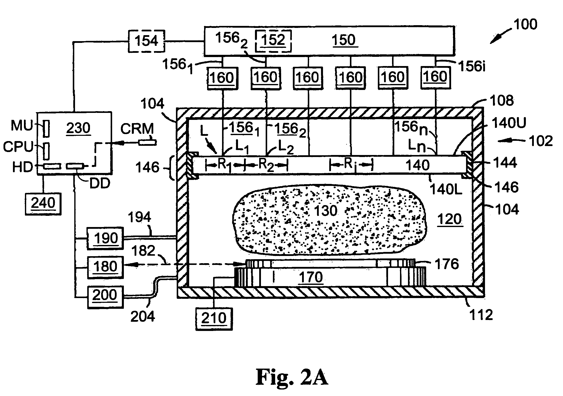
[0029]With reference to FIG. 2A, plasma reactor system 100 comprises reactor chamber 102 with sidewalls 104, an upper wall 108 and a lower wall 112 defining an interior region 120 capable of supporting plasma 130. Arranged within interior region 120 near upper wall 108 is a unitary electrode 140 having an upper surface 140U and a lower surface 140L and a periphery 144. Electrode 140 is referred to as the “plasma electrode”. Insulators 146 are arranged between electrode periphery 144 and sidewalls 104 to electrically isolate electrode 140 from chamber 102. System 100 further includes a RF power multiplexer 150. A RF power supply 152 is included in RF multiplexer 150. Alternatively, an external RF power supply (as illustrated by RF power supply 154) is provided.

[0030]FIG. 2B shows an exemplary layout of a mu...


PUM

PropertyMeasurementUnit
driving frequencyaaaaaaaaaa
frequencyaaaaaaaaaa
frequencyaaaaaaaaaa

Abstract

A method and apparatus for generating and controlling a plasma (130) formed in a capacitively coupled plasma system (100) having a plasma electrode (140) and a bias electrode in the form of a workpiece support member (170), wherein the plasma electrode is unitary and has multiple regions (Ri) defined by a plurality of RF power feed lines (156) and the RF power delivered thereto. The electrode regions may also be defined as electrode segments (420) separated by insulators (426). A set of process parameters A={n, τi, Φi, Pi, S; Li} is defined; wherein n is the number of RF feed lines connected to the electrode upper surface at locations Li, τi is the on-time of the RF power for the ith RF feed line, Φi is the phase of the ith RF feed line relative to a select one of the other RF feed lines, Pi is the RF power delivered to the electrode through the ith RF feed line at location Li, and S is the sequencing of RF power to the electrode through the RF feed lines. One or more of these parameters are adjusted so that operation of the plasma system results in a workpiece (176) being processed with a desired amount or degree of process uniformity.

Description

[0001]This is a divisional application of U.S. application Ser. No. 10 / 359,557, filed on Feb. 7, 2003, which is a continuation of International Application No. PCT / US01 / 24491, filed on Aug. 6, 2001, which, in turn, claims benefit of U.S. application No. 60 / 223,834, filed Aug. 8, 2000, the contents of all of which are incorporated herein in their entirety by reference.BACKGROUND OF THE INVENTION[0002]The present invention pertains to plasma processing of workpieces, and in particular pertains to a method and apparatus for improving the uniformity of plasma processing.[0003]Ionized gas or “plasma” may be used during processing and fabrication of semiconductor devices, flat panel displays and other products requiring etching or deposition of materials. Plasma may be used to etch or remove material from semiconductor integrated circuit wafers, or to sputter or deposit material onto a semiconducting, conducting or insulating surface. Creating a plasma for use in manufacturing or fabricat...

Claims


Application Information

Patent Timeline
Patent Type & Authority Patents(United States)
IPC IPC(8): H05B31/26C23F1/00H01J37/32
CPCH01J37/32009H01J37/32082H01J37/32935H01J37/32532H01J37/32091
Inventor MITROVIC, ANDREJ S.STRANG, ERIC J.SIRKIS, MURRAY D.QUON, BILL H.PARSONS, RICHARDTSUKAMOTO, YUJI
Owner TOKYO ELECTRON LTD
Why Eureka
Try Eureka