Circuit arrangement for operating discharge lamps

Inactive Publication Date: 2007-01-16
KONINKLIJKE PHILIPS ELECTRONICS NV
View PDF4 Cites 20 Cited by
  • Summary
  • Abstract
  • Description
  • Claims
  • Application Information

AI Technical Summary

Benefits of technology

[0008]The invention aims to provide a circuit arrangement that is capable of operating two lamps i

Problems solved by technology

In a full bridge the control circuit is more complicated than in a half bridge since the conductive state of four switching elements instead of only two switching elements needs to be controlled.
The voltage across the load circuit of a half bridge powered by the same supply voltage source will generally not be high enough to operate such a series arrangement of lamps.
A disadvantage of the full bridge is that, because of the two additional switches and the more complicated control circuit, it is mo

Method used


Image

  • Circuit arrangement for operating discharge lamps
  • Circuit arrangement for operating discharge lamps

Examples


Embodiment Construction

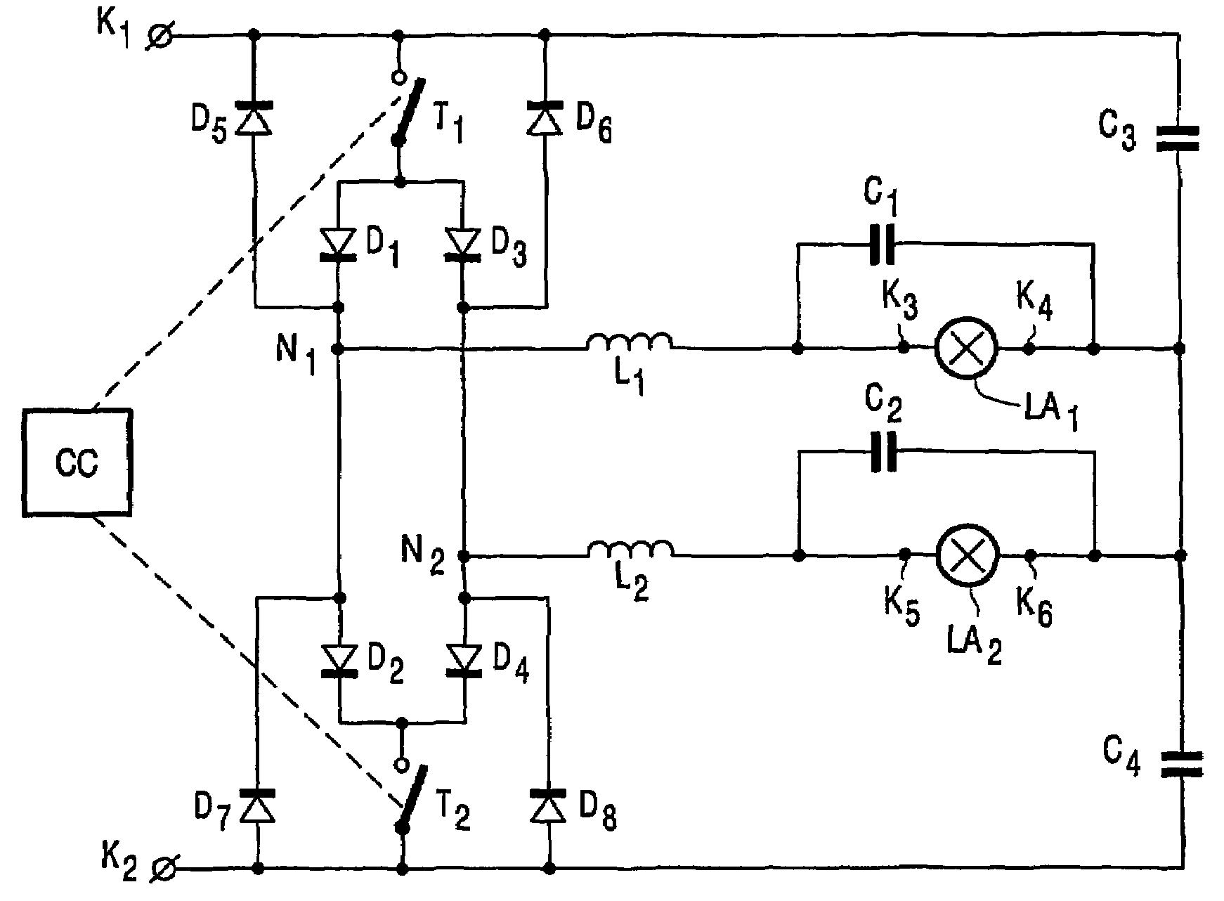
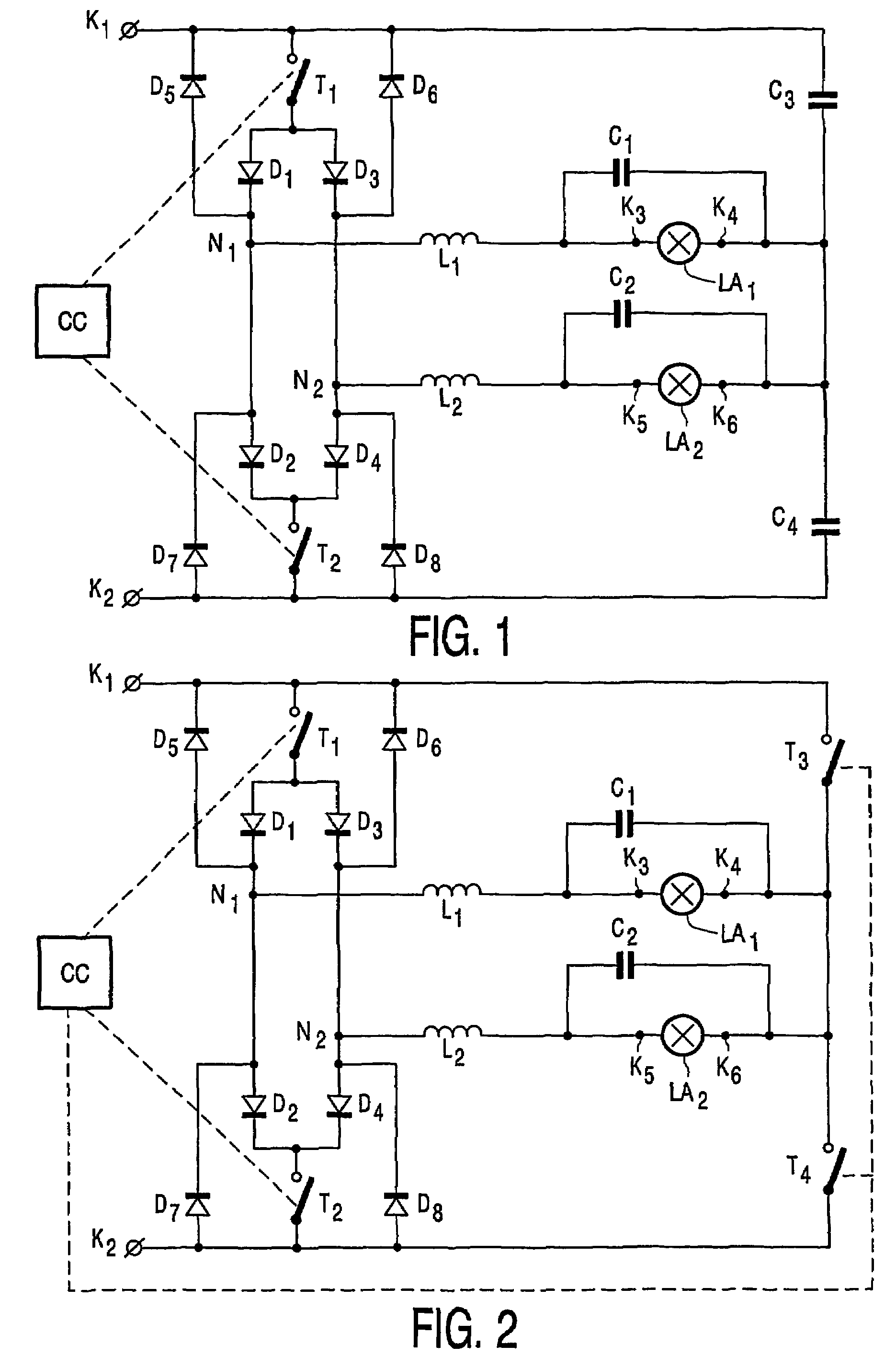
[0024]In FIG. 1, K1 and K2 are input terminals for connection to a supply voltage source. Input terminals K1 and K2 are connected by means of a series arrangement of first switching element T1, diode D1, terminal N1, diode D2 and switching element T2. Diodes D1 and D2 respectively form a first and a second diode. Diodes D1 and D2 together with terminal N1 form a series arrangement III connecting the first and the second switching element. Series arrangement III is shunted by a series arrangement of diode D3, terminal N2 and diode D4. Diodes D3 and D4 respectively form a third and a fourth diode. Diodes D3 and D4 together with terminal N2 form a series arrangement IV connecting the first and the second switching element. The first switching element T1, the second switching element T2 and the parallel arrangement of series arrangements III and IV together form a series arrangement I. The series arrangement of diode D1 and first switching element T1 is shunted by diode D5 that forms a ...


PUM


Abstract

A DC-AC converter in a half bridge configuration is used for operation with high pressure discharge lamps as well as low pressure discharge lamps. The converter consists in two switches (T1-T2) serially connected through a first series of diodes (D1, D2) and a second series of diodes (D3,D4) to which at their middle points (N1, N2) a first and a second lamp loads (L1,L2,LA1,LA2) are connected. Furthermore, the second terminals of the lamp loads are connected to the middle point of a series of capacitors (C3,C4) which are also connected to the terminals (Ki,K2) of the supply voltage source. The converter includes also four diodes (D5,D6,D7,D8) which shunt the switches (T1,T2) and their respective series of diodes (D1,D2,D3,D4). The switches (T1,T2) are controlled by a controller (CC) which renders alternatively conductive at low frequency the two switches (Ti,T2). In the first operating state, the first switch (T1) is rendered conductive and non-conductive at a high-frequency while the second switch (T2) is maintained in a non-conductive state, in the second operating state the second switch (T2) is rendered conductive and non-conductive at high-frequency while the first switch (T1) is maintained in a non-conductive state. The series of two capacitors (C3,C4) can be replaced by a series of two switches (T3,T4) in order to obtain a full bridge configuration of the converter. The particular configuration of the network and its operating mode allow to drive the lamp loads in such a way that the difference in power consumed by the lamps is comparatively small.

Description

FIELD OF THE INVENTION[0001]The invention relates to a circuit arrangement for operating a lamp load comprising[0002]input terminals for connection to a supply voltage source,[0003]a series arrangement I comprising a first switching element and a second switching element and connecting the input terminals,[0004]a control circuit coupled to respective control electrodes of the first switching element and the second switching element for controlling the conductive state of the first and the second switching element,[0005]a series arrangement II comprising a first circuit element A and a second circuit element B and connecting the input terminals,[0006]a first load circuit comprising a first ballast inductor and first lamp connection terminals and connecting a terminal N1 of the series arrangement I between the switching elements to a terminal of the series arrangement II between the first circuit element A and the second circuit element B.BACKGROUND OF THE INVENTION[0007]Such a circui...

Claims


Application Information

Patent Timeline
IPC IPC(8): H05B37/02H05B41/282H05B41/288
CPCH05B41/2827H05B41/2883H05B41/2888Y10S315/05Y02B20/202Y10S315/07Y02B20/00
Inventor VAN CASTEREN, DOLF HENRICUS JOZEF
Owner KONINKLIJKE PHILIPS ELECTRONICS NV
Why Eureka
Try Eureka