
System and method for time-space multiplexing in finger-imaging applications

a time-space multiplexing and fingerprint image technology, applied in image data processing, instruments, computer peripheral equipment, etc., can solve the problems of reducing the number of captured fingerprint images, and limiting the number of captured fingerprints. achieve the effect of reducing the size and cost of implementation

Active Publication Date: 2007-01-16
PIXART IMAGING INC
View PDF47 Cites 25 Cited by
  • Summary
  • Abstract
  • Description
  • Claims
  • Application Information

AI Technical Summary

Benefits of technology

[0015]Using a single sensing area to provide image data for both finger recognition and finger navigation applications reduces the size and cost of implementing these applications onto an electronic device. In addition, by making the sensing area smaller than the conventional 9×12 mm sensing area used for finger recognition, a finger recognition application can be implemented on small and / or portable electronic devices, such as cell phones, laptop computers, personal digital assistants and electronic mice. Furthermore, the invention provides embodiments with other features and advantages in addition to or in lieu of those discussed above. Many of these features and advantages are apparent from the description below with reference to the following drawings.

Problems solved by technology

However, in smaller area and / or lower resolution fingerprint imaging applications, the finger-recognition algorithmic performance is usually inferior due to the reduction in the number of captured features.
For some applications, dedicating an area of even 9×12 mm to capture a fingerprint image is undesirable.
However, there is not currently a fingerprint scanner available that has a small enough sensing area for implementation on such electronic devices, while still enabling adequate finger-recognition algorithmic performance.
Placing separate sensing areas for finger recognition and finger navigation on the same electronic device is inefficient from both a cost perspective and a space perspective.
However, there is not currently a fingerprint scanner available capable of performing both finger recognition and finger navigation.

Method used


Image

  • System and method for time-space multiplexing in finger-imaging applications
  • System and method for time-space multiplexing in finger-imaging applications
  • System and method for time-space multiplexing in finger-imaging applications

Examples


Embodiment Construction

[0041]The numerous innovative teachings of the present application will be described with particular reference to exemplary embodiments. However, it should be understood that these embodiments provide only a few examples of the many advantageous uses of the innovative teachings herein. In general, statements made in the specification do not necessarily delimit any of the various claimed inventions. Moreover, some statements may apply to some inventive features, but not to others.

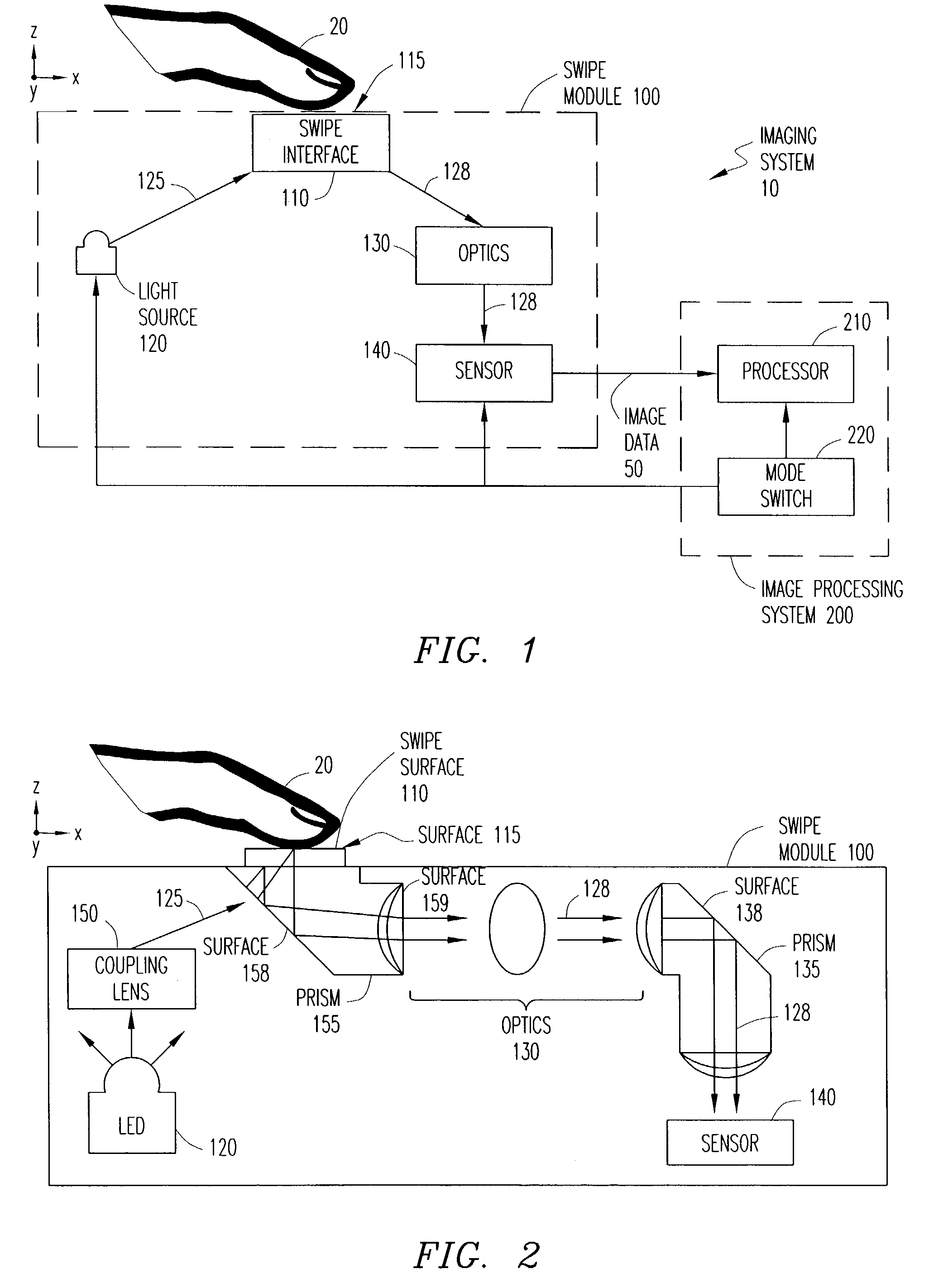
[0042]FIG. 1 illustrates an imaging system 10 capable of operating in at least two different modes, one of which is a finger navigation mode and another of which is a finger recognition mode. Other modes are possible, depending on the application of the imaging system 10. For example, the imaging system 10 can be programmed to operate in a stylus mode, in which finger strokes are used to represent written letters, numbers, punctuation marks and other written forms of communication in a convenient and efficie...


PUM


Abstract

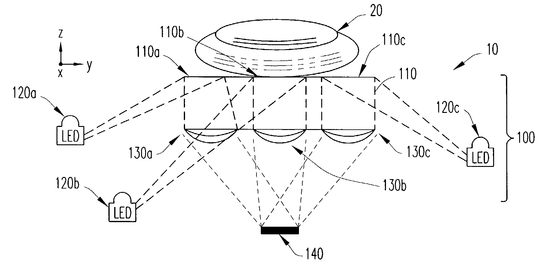
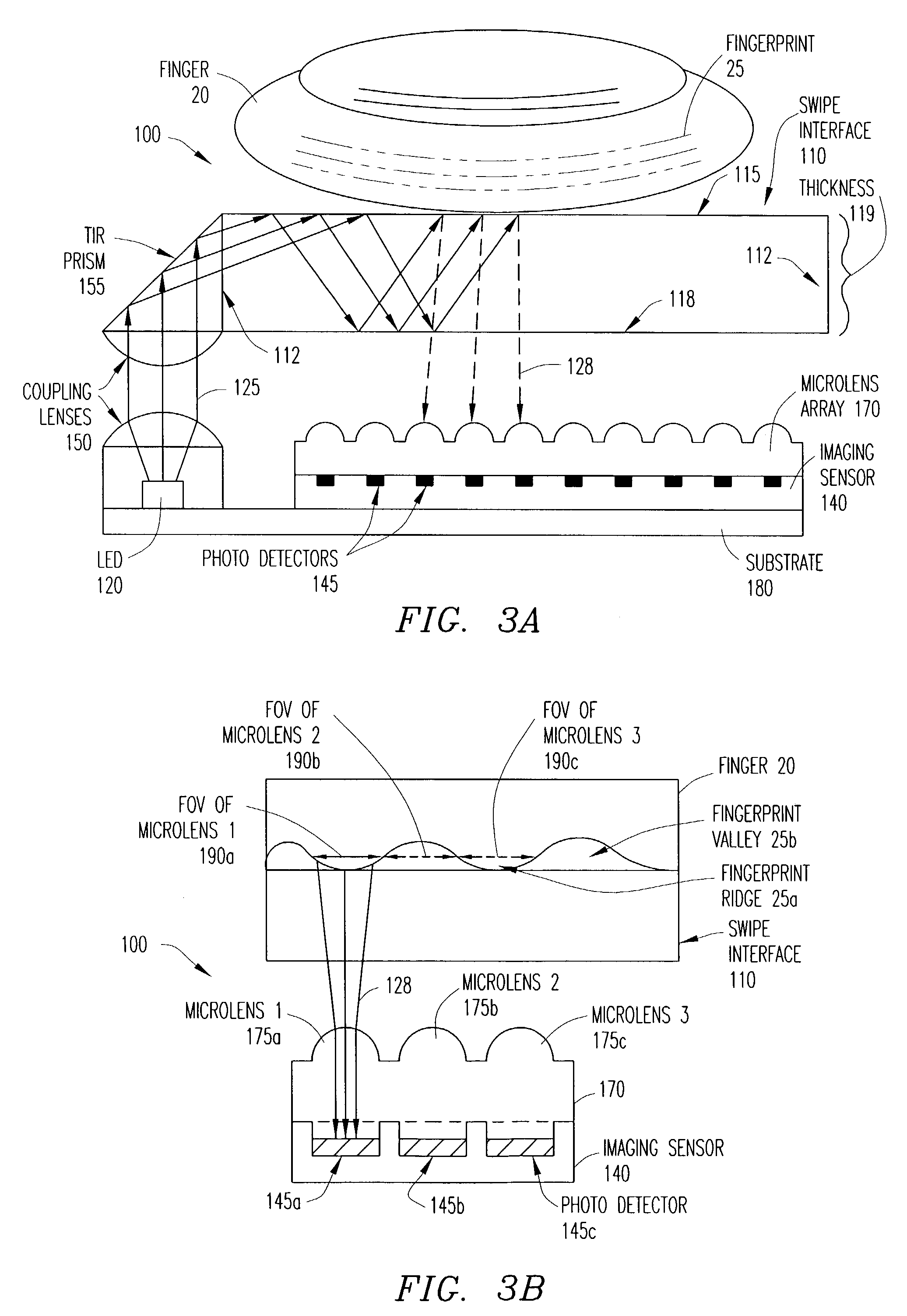
An apparatus for imaging a fingerprint operates in a selected mode to provide a finger recognition and / or a finger navigation application. Multiple light sources are capable of being sequentially selected for illumination of corresponding partitions of a finger interface upon which a user places a finger (or thumb). The selection of light sources is based on the selected mode of operation. A single sensor captures light reflected from the digit in all illuminated partitions as sequential partition images. The sensor further outputs image data corresponding to the captured partition images for processing in the selected mode.

Description

CROSS-REFERENCE TO RELATED APPLICATIONS[0001]This U.S. Nonprovisional for Patent is related by subject matter to copending and commonly assigned U.S. Nonprovisional for Patents Ser. Nos. 10 / 419,226 and 10 / 418,968 filed on even date herewith. U.S. Nonprovisional for Patents Ser. Nos. 10 / 419,226 and 10 / 418,968 are hereby incorporated by reference in their entirety.BACKGROUND OF THE INVENTION[0002]1. Technical Field of the Invention[0003]The present invention relates generally to the field of image acquisition. More specifically, the present invention relates to systems and methods for obtaining and processing images of fingerprints for navigation and recognition purposes.[0004]2. Description of Related Art[0005]The use of fingerprints for identification purposes can be dated back for centuries. For example, in 14th century Persia, various official government papers included fingerprints (impressions), and one government official observed that no two fingerprints were exactly alike. In...

Claims


Application Information

Patent Timeline
Patent Type & Authority Patents(United States)
IPC IPC(8): G06K7/00G06K9/00G06K9/20G06T1/00G06F3/03G06F3/033G06F3/0354G06F3/038G06F3/041
CPCG06F3/0317G06F3/03547G06K9/00067G06K9/00026G06K9/00046G06F2203/0338G06V40/1335G06V40/1324G06V40/1347
Inventor BAHARAV, IZHAKMACHIDA, AKIHIROSMITH, GEORGE E.
Owner PIXART IMAGING INC
Learn More