Flexible material tri-wedge bar and clamp assembly for use with a tensioning device

a technology of flexible material and clamp assembly, which is applied in the direction of snap fasteners, instruments, boards, etc., can solve the problems of deformation of material, material tearing, damage to flexible material, etc., and achieve the effect of minimal strain on flexible material and maximum gripping properties

Active Publication Date: 2007-01-23
COLEMAN KELLY R
View PDF9 Cites 16 Cited by
  • Summary
  • Abstract
  • Description
  • Claims
  • Application Information

AI Technical Summary

Benefits of technology

[0012]Accordingly, it is an object of the present invention to provide an improved clamp assembly for retaining a flexible material in a cavity with maximum gripping properties while applying minimal strain on the flexible material.
[0013]Another object of this invention is the utilization of a triangular bar in combination with a rigid nonflexibleclamp having a triangular channel to secure a flexible material wound about the triangular bar within the channel. When the wrapped bar is inserted in the triangular channel, the flexible material is passed outside the clamp through the apex of its channel. When tension is applied to the flexible material tending to pull it out of the clamp channel or when the clamp body is drawn in the opposite direction, the triangular bar will be drawn toward the apex of the channel with its major surfaces contacting the major surfaces of the channel. As it is so drawn, a gripping force is applied gradually and distributed evenly to the flexible material wrapped about the bar at every point on the major surfaces of the triangular bar. The major surfaces of the triangular bar distribute the tensile force to the major surfaces of the channel in the same manner as an inclined plane. That is, when a force acts on the triangular bar along a line from its apex to the center of its base, as would happen when tension is applied to the flexible material or when an opposite force is applied to the clamp body, this force would be distributed perpendicularly throughout the entire surface area of the bar's major surfaces toward the adjacent walls of the clamp channel resulting in a smooth application of the gripping force with minimal pulling on the material. This is especially important for flexible material that could be subject to tearing or deformation. The use of this triangular bar and triangular clamp channel provide outstanding hold performance, provides a more positive lock and as noted above a smooth gripping force that is spread out over the widest possible area. Theoretically, the smaller the acute angle of the triangular bar and channel cavity, the greater the surface area of the major surfaces and therefore the greatest distribution of the gripping force.
[0015]A further object of the invention is to use the improved clamp assembly with a C-channel tensioning receiver with teeth or grooves on the inside of one of its walls. The improved clamp assembly is provided with teeth or grooves on one of its external walls. The clamp assembly is inserted into the C-channel tensioning means with the clamp assembly's opening at the channel apex facing the closed end of the C-channel and the flexible material passing between the non-toothed C-channel wall and non-toothed clamp exterior surface. As the clamp and C-channel ratchet relative to one another, the flexible material becomes tensioned and locks the material within the clamp channel. As the clamp continues into the C-channel, the tensioned material causes the clamp to rotate and further clamp the flexible material between the C-channel wall and the external surface of the clamp thereby providing a second locking action on the flexible material.

Problems solved by technology

Although the material is secured, such physical deformation clearly could damage the flexible material.
If the clip fails for whatever reason, and they are known to do so, it could result in slippage of the material from the cavity, severe stress to the material resulting in deformation of the material, and in some instances tearing of the material.
Since many of these prior art clips are made from flexible material, particularly in the area where they secure the fabric, when this part of the clip fails, so does its grip on the fabric.
If either of these legs fail, the uniform grip on the fabric is lost and the stress in the fabric will cause slippage of the fabric or, at the very least, distortion of the fabric being tensioned.
Should this clip fail or just the small prongs of the clip fail, the fabric would slip or deform and the uniform tensioning would be lost.
Furthermore, this reference fails to teach the unique additional external clamping or locking of the fabric margin between the external portion of the clamp as well as the clamping or locking by the apex of the triangular bar.

Method used


Image

  • Flexible material tri-wedge bar and clamp assembly for use with a tensioning device
  • Flexible material tri-wedge bar and clamp assembly for use with a tensioning device
  • Flexible material tri-wedge bar and clamp assembly for use with a tensioning device

Examples


Embodiment Construction

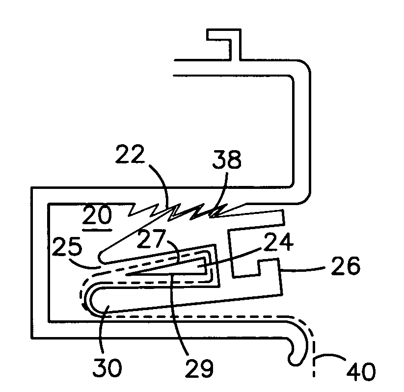
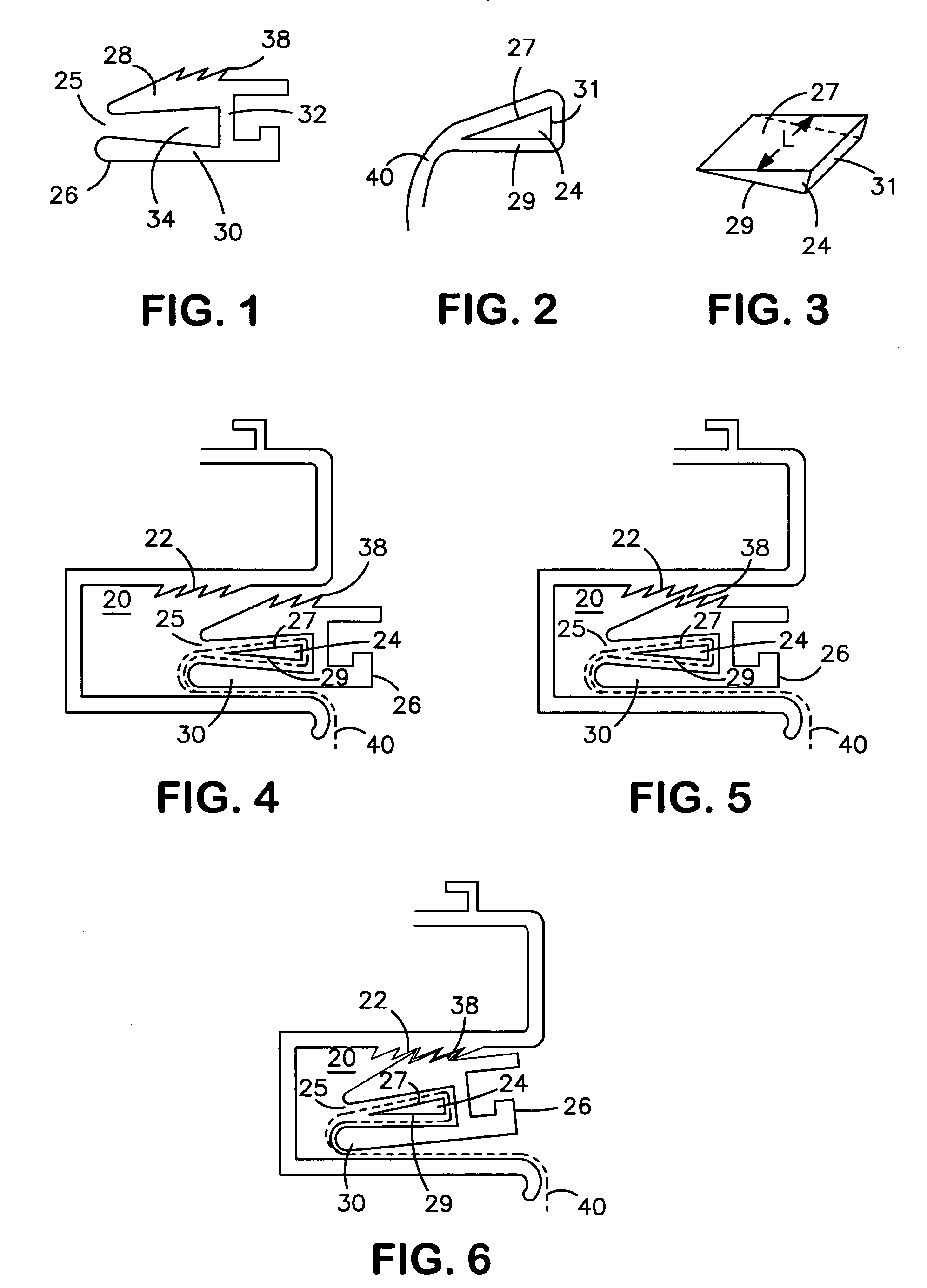
[0030]The subject of the present invention is an improvement to the tensioning assembly utilized in the Coleman U.S. Pat. No. 5,398,388 incorporated herein by reference. In the latter patent, a straight line ratchet is created by virtue of a formed receiver C-channel open area 20 with grooves or teeth 22, or a channel fitted with grooves may be incorporated as part of a sign embodiment or it may be provided as a part to attach to an existing sign embodiment or other structure. This prior art is shown in FIG. 9.

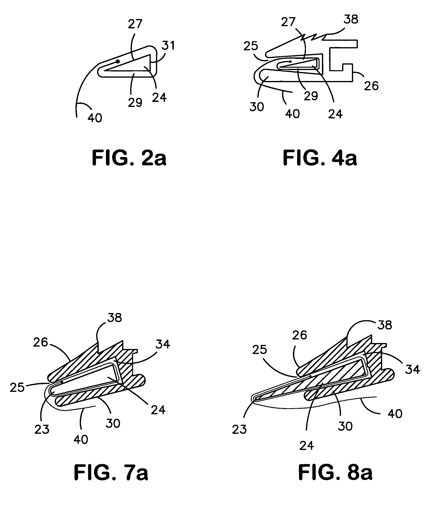
[0031]In place of the tensioning bar and clamp utilized in the above patent, the improved tensioning apparatus is made up of two parts as shown in FIGS. 1–3. The first part shown in FIGS. 2–3 consists in a tapered triangular bar 24, which has two major surfaces 27 and 29 meeting at an acute angle and a base 31. Although the figures show the edges as sharp, they also could be slightly rounded to protect the flexible material. The major surfaces 27 and 29 of the bar may be smoot...


PUM


Abstract

Flexible material clamp discloses two parts, triangular bar and rigid clamp having congruent triangular channel. The bar has base and two major inclined surfaces meeting at acute angle, length of the major surfaces being at least three times base height. Clamp has internal triangular channel whose major surfaces are congruent to major surfaces of triangular bar. One clamp end opens into apex of the channel and at least one side of clamp opens to triangular channel. One end of flexible material to be clamped is wrapped about triangular bar and overlapped upon itself. The wrapped bar is inserted into clamp channel though the at least one open side of clamp and flexible material is passed through clamp opening at channel apex. Assembled wrapped bar and clamp connect to tensioning means causing clamp and bar to move relative to one another to lock flexible material between major surfaces of triangular bar and corresponding major surfaces of triangular clamp channel, locking flexible material in channel.

Description

BACKGROUND OF THE INVENTION[0001]1. Field of the Invention[0002]The invention relates to a clamp assembly for releasable securing a flexible material within the clamp assembly and the use of this clamp assembly to tension or support the flexible material and is particularly useful in the tensioning of flexible material signs, awnings, screens, etc.[0003]2. Description of the Prior Art[0004]This invention is an improvement to the tensioning assembly utilized in Coleman U.S. Pat. No. 5,398,388 to make a sign facing formed of flexible material tight against a sign frame.[0005]It is known in this art to provide a means for securing the edges of flexible material, be it a sign, an awning, a screen, a silkscreen etc., to some form of clip or clamp and then to use the clips with a frame structure to tension the flexible material across the frame. All these clips are provided with some form of cavity that is designed to receive the edge of the flexible material and retain the material there...

Claims


Application Information

Patent Timeline
Patent Type & Authority Patents(United States)
IPC IPC(8): A44B11/25G09F17/00A44B99/00
CPCF16B5/0692G09F15/0025Y10T24/4406
Inventor COLEMAN, KELLY R.
Owner COLEMAN KELLY R
Why Eureka
Try Eureka