Method for running in a drive train component of a wind energy plant and wind energy plant for executing this method

a technology of wind energy plants and drive trains, which is applied in the direction of adaptive control, non-positive displacement fluid engines, liquid fuel engine components, etc., can solve the problems of limited lifetime of individual drive train components, high mechanical strain on the components of such a drive train, and strong strain on the gearings of the gearbox in particular

Inactive Publication Date: 2010-11-16
NORDEX ENERGY
View PDF16 Cites 2 Cited by
  • Summary
  • Abstract
  • Description
  • Claims
  • Application Information

AI Technical Summary

Benefits of technology

[0012]This procedure results in a limitation of the mechanical strain of the drive train component, which depends on the strain accumulated since starting up the drive train component The strains actually acting on the drive train component are limited by this, such that a particularly good matching of surfaces being in engagement, like the frictional pairings in the bearings and on the tooth faces, and a particularly gentle, continuous running in is achieved. The method of the present invention is advantageous in particular in order to smooth gearings and to ascertain the reliability thereof. An overstrain of the tooth faces when starting up is effectively prevented. Through this, the obtainable lifespan of the drive train component is prolonged.
[0016]In a further embodiment, the maximum value BMax has an initial value BF when the drive train component is started up. Thus, there is no limitation of the desired value BS to values below the minimum value preset by the initial valueBF. As a consequence, a minimum strain of the drive train component corresponding to this initial value BF is permitted, beginning with the start-up of the drive train component. Through this, an excessive limitation of the operational variable is avoided.

Problems solved by technology

All the components of such a drive train are exposed to high mechanical strains, the gearings of the gearbox in particular are strongly strained by the high torques of the rotor.
As a consequence, in spite of the intense efforts of the manufacturers of wind energy plants and gearboxes, respectively, damages in the drive train region occur always again, which can lead to the breakdown of the wind energy plant The high strains lead also to a limited lifetime of individual drive train components, which can make a replacement of the components necessary, as the case may be.
Such a replacement is accompanied by a high expense of money and time and leads to an unwanted failure of the wind energy plant.

Method used


Image

  • Method for running in a drive train component of a wind energy plant and wind energy plant for executing this method
  • Method for running in a drive train component of a wind energy plant and wind energy plant for executing this method
  • Method for running in a drive train component of a wind energy plant and wind energy plant for executing this method

Examples


Embodiment Construction

[0030]While this invention may be embodied in many different forms, there are described in detail herein a specific preferred embodiment of the invention. This description is an exemplification of the principles of the invention and is not intended to limit the invention to the particular embodiment illustrated

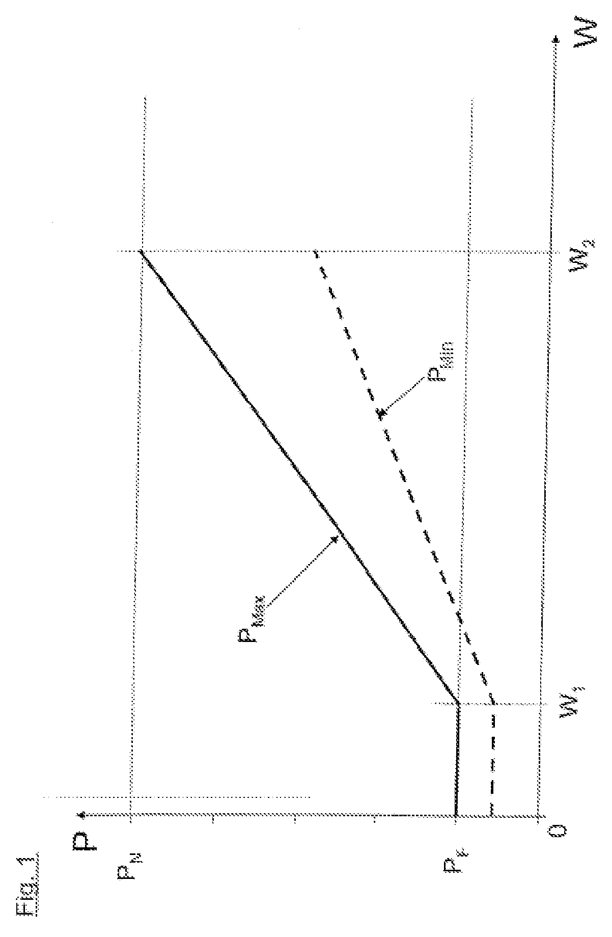
[0031]On the abscissa of the coordinate system shown in FIG. 1, the yield value W is plotted. On the ordinate of the coordinate system, the electric power P provided by the wind energy plant is indicated. On the basis of the relation depicted in the diagram, one maximum value of the power PMax is assigned to every yield value W, which is used for the limitation of the desired value PS of the power. Further, one minimum value PMin is assigned to every yield value W, which represents a lower limit for a power to be classified as relevant for running in.

[0032]The curve for the maximum value PMax begins with a yield value W of 0 at an initial value PF, which is about ⅕ of the also...


PUM


Abstract

A method for running in a drive train component of a wind energy plant, wherein the wind energy plant has an operation management which can control at least one operational variable B significant for the strain of the drive train component to a desired value BS, wherein after starting up the drive train component, the desired value BS is limited by a maximum value BMax, which is preset depending on a yield value W which describes the yield of the wind energy plant achieved since starting up the drive train component.

Description

CROSS-REFERENCE TO RELATED APPLICATIONS[0001]Not applicable.STATEMENT REGARDING FEDERALLY SPONSORED RESEARCH[0002]Not applicable.BACKGROUND OF THE INVENTION[0003]The present invention is related to a method for running in a drive train component of a wind energy plant and a wind energy plant which can execute this method.[0004]The drive train of a wind energy plant transmits the torque of a rotor of the wind energy plant, which is driven by the wind, to a generator which provides electric energy. In the case of a directly driven generator, the same can be immediately connected to the rotor via a shaft. However, in the most frequent construction, the generator is operated at a rotational speed which is substantially higher than that of the rotor, so that a step-down gearbox is needed in the drive train. Such gearboxes are normally realised with two or three steps and have a number of gearings in engagement with each other. All the components of such a drive train are exposed to high ...

Claims


Application Information

Patent Timeline
Patent Type & Authority Patents(United States)
IPC IPC(8): F03D9/00B63H7/00G05B13/02G05D3/12G05D17/00F03D7/02H02P9/04F04D27/02B64C11/00B64C27/00
CPCF03D7/026F03D7/0292F05B2270/109G05B2219/2619Y02E10/723F05B2270/1095Y02E10/72
Inventor NITZPON, JOACHIMKARSTENS, HAUKEHARMS, ULRICH
Owner NORDEX ENERGY
Why Eureka
Try Eureka