Process and device for separating and exhausting gas bubbles from liquids

a technology of gas bubbles and liquids, applied in the field of microfluidic systems, can solve the problems of not being suited for gas separation independent of position, known filter arrangement not working completely independently of position, etc., and achieve the effect of simple and effective manner

Active Publication Date: 2007-01-23
BOEHRINGER INGELHEIM MICROPARTS
View PDF8 Cites 11 Cited by
  • Summary
  • Abstract
  • Description
  • Claims
  • Application Information

AI Technical Summary

Benefits of technology

[0013]A primary object of the present invention is to devise a process and a device for separating and exhausting gas bubbles from a flowing liquid so that separation of gas bubbles from the liquid can take place independently of position in a very effective and simple manner.
[0014]The aforementioned object is achieved by a process in accordance with the present invention by the flow path of the liquid being deflected between the inlet point and the deaeration chamber and between the deaeration chamber and the discharge point so that the liquid is first deflected radially outward from the axial direction into the deaeration chamber, and then, radially inward back into the axial direction. For the device of the invention, the aforementioned deflection can be accomplished very easily by the deaeration chamber being made at least essentially annular. Thus, the gas can be separated from the liquid through the gas separation material at least for the most part independently of the position.
[0016]In the deaeration chamber, through which liquid flows in accordance with the invention, in a first version, there is a minor backpressure as a result of the discharge filter which adjoins the deaeration chamber; the filter being made of a material which absorbs the liquid and which forms pores or small channels. The gas bubbles can be exhausted from the liquid through the wall or the wall section of gas separation material from the deaeration chamber, this material even preventing passage of liquid. As a result of the pressure which prevails in the deaeration chamber and which is further increased by the discharge filter relative to ambient pressure, exhausting of the gas bubbles is comparatively effective. Moreover, in any case, the gas bubbles are also displaced from the discharge filter itself to the outside when there is a wall section of gas separation material on the discharge filter. The liquid which has been sucked into the discharge filter leads to displacement of the gas bubbles out if they had entered the discharge filter at all.
[0017]In another version, first a liquid flows through an inlet filter, likewise made of a material which absorbs the liquid and which forms pores or small channels. This inlet filter, as a result of its properties, also becomes completely soaked with liquid and increases the effectiveness of gas separation when it is bordered by at least one wall or a wall section of gas separation material. Gas bubbles can then be exhausted to the outside on a direct path from the inlet filter.
[0019]The device in accordance with the invention makes it possible to separate and exhaust gas bubbles from a liquid independently of position. The device can be inserted into a line arrangement which carries the liquid and can operate without interruption. The device according to the invention operates passively; therefore, the device does not require an additional external energy source. Due to the skillful choice of operating elements, the pressure drop is comparatively small as the liquid flows through.

Problems solved by technology

The disadvantage is that the known filter arrangement does not work completely independently of position.
It is not suited for gas separation independent of position.

Method used


Image

  • Process and device for separating and exhausting gas bubbles from liquids
  • Process and device for separating and exhausting gas bubbles from liquids
  • Process and device for separating and exhausting gas bubbles from liquids

Examples


Embodiment Construction

[0029]In the figures, the same reference numbers are used for the same or similar components of the various embodiments that have the same or similar properties or advantages.

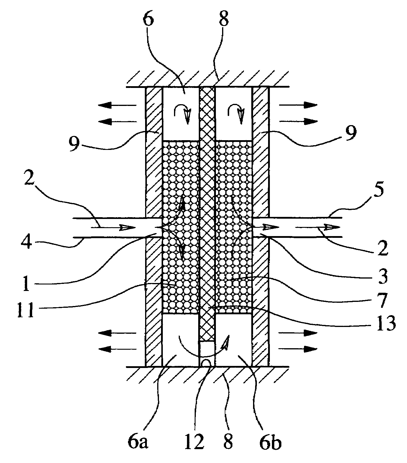
[0030]FIG. 1 shows the basic principle of gas separation. The device shown there will be explained first with reference to the flow direction of the liquid which is indicated by the solid line arrow on the left.

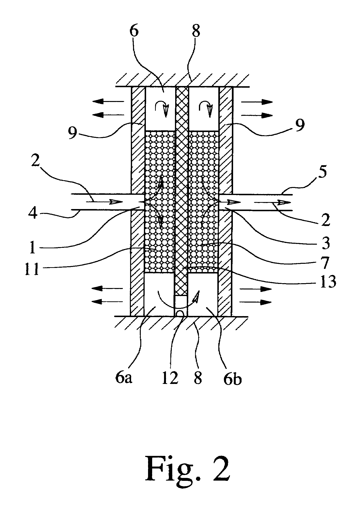
[0031]The device is used for separating and exhausting gas bubbles from a flowing liquid, especially in a microfluidic system. There are an inlet point 1 for the entry of a liquid 2 which contains gas bubbles and a discharge point 3 for discharge of this liquid 2 from the device.

[0032]FIG. 2 indicates a connecting line 4 which leads to the inlet point 1, and a connecting line 5 which leads away from the discharge point 3. The connecting lines 4, 5 can be hoses, rigid lines, flow channels in a chip, etc. It is important that the liquid 2 which contains the gas bubbles on the route from the inlet point 1 t...


PUM

PropertyMeasurementUnit
angleaaaaaaaaaa
thicknessaaaaaaaaaa
thicknessaaaaaaaaaa

Abstract

A process and a device for separating and exhausting gas bubbles from a flowing liquid, especially in a microfluidic system, are proposed. Radial deflection of the liquid, a preferably annular deaeration chamber from which gas can escape through gas separation material, and a following discharge filter are characteristic. The discharge filter is made of a hydrophilic material which forms pores or small channels. Optionally, there is an inlet filter of the corresponding material upstream of the deaeration chamber.

Description

BACKGROUND OF THE INVENTION[0001]1. Field of the Invention[0002]The invention relates to a process for separating and exhausting gas bubbles from a flowing liquid, especially in a microfluidic system, in which the liquid which contains gas bubbles flows through a deaeration chamber on the way from an inlet point to a discharge point, and to a corresponding device with an inlet point for the entry of a liquid containing gas bubbles and a discharge point for the discharge of the liquid from the device, with a deaeration chamber downstream of the inlet point in the flow direction of the liquid.[0003]2. Description of Related Art[0004]In the process known from microfluidics, the separation of gas bubbles from liquids is achieved in that the water-based liquid which contains gas bubbles flows through a a deaeration chamber which has a wall section of a water-repellent gas separation material which is not permeable to the liquid, but which is permeable to the gas. With this known process,...

Claims


Application Information

Patent Timeline
Patent Type & Authority Patents(United States)
IPC IPC(8): B01D19/00B01D61/00
CPCB01D19/0031
Inventor VESPER, CHRISTIANYU, YINGPETERS, RALF-PETERSTOETERS, WOLFGANG
Owner BOEHRINGER INGELHEIM MICROPARTS
Why Eureka
Try Eureka