
Image requesting apparatus

a technology for requesting apparatus and images, applied in the field of multimedia description data, can solve the problems of reducing communication time, unfavorable communication time or communication fee, and contributing to the reduction of communication time, so as to reduce the amount of communication and communication time

Inactive Publication Date: 2007-01-23
CANON KK
View PDF19 Cites 7 Cited by
  • Summary
  • Abstract
  • Description
  • Claims
  • Application Information

AI Technical Summary

Benefits of technology

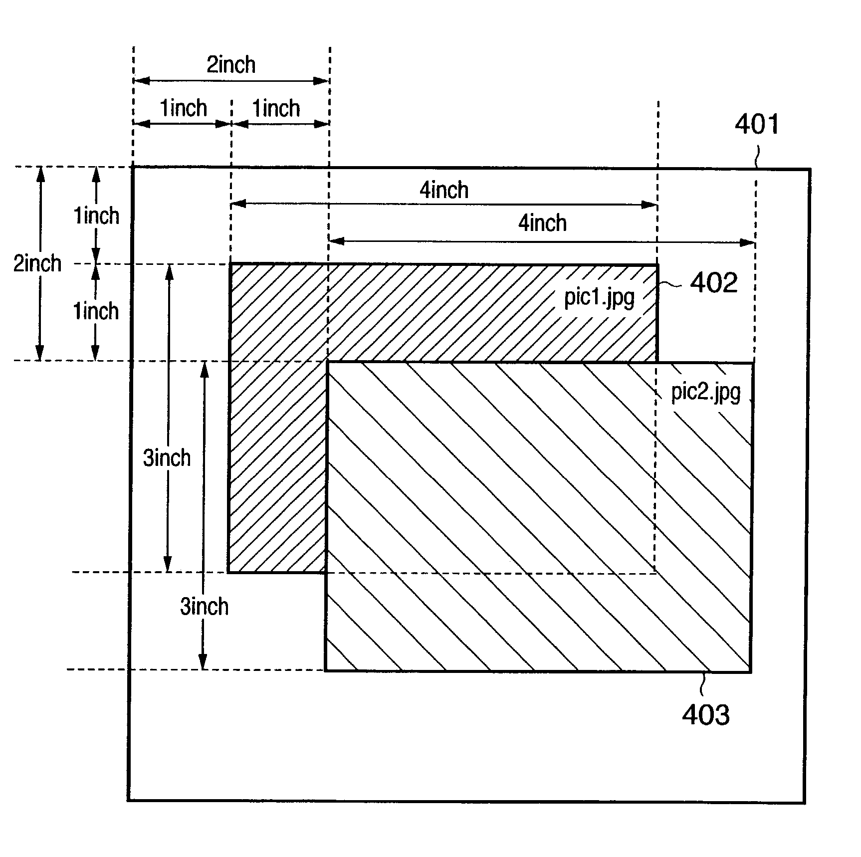
[0015]The present invention has been made to solve the above problems, and has as its object to reduce the communication amount and communication time by neither transmitting nor receiving image data of an overlapped portion of one of a plurality of images and another image.

Problems solved by technology

Therefore, if the line speed between the server and client is low or if the communication is charged, the communication time or communication fee undesirably exceeds the originally necessary time or fee.
However, this method still has the following problems.(1) Specifications of the current standards of HTML / XHTML and style sheets are ambiguous and depend on an interpreter (e.g., a browser).
Therefore, a layout actually determined by a target interpreter does not match the prediction by the author in some cases.(2) Conflicts occur if a layout dynamically changes, e.g., if the size of image data to be referred to or an overlying graphic object changes each time, of if an interpreter can dynamically change the layout of graphic objects.
Unfortunately, either processing is performed after graphic object data (image data if the object is an image) to be deleted is received, and hence does not contribute to reduction of the communication time described above.

Method used


Image

  • Image requesting apparatus
  • Image requesting apparatus
  • Image requesting apparatus

Examples


first embodiment

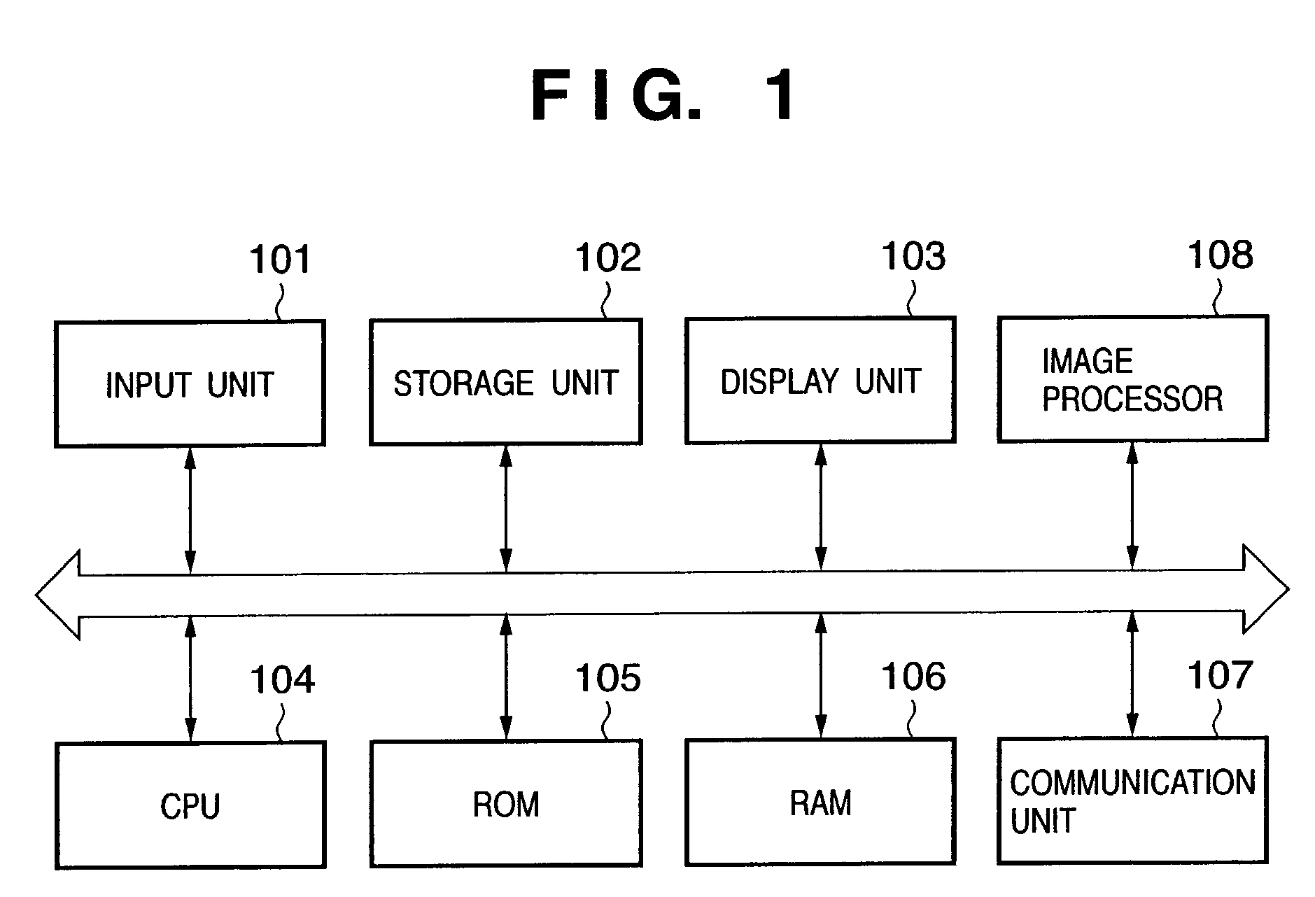
[0053]FIG. 1 is a block diagram showing the arrangement of an image communication apparatus forming an image communication system. An input unit 101 shown in FIG. 1 is a device for inputting instructions and data from a user, and includes a keyboard, pointing device, and the like. Examples of the pointing device are a mouse, trackball, track pad, and tablet. When this apparatus is applied to a well-known digital camera, the input unit 101 can be a button, mode dial, or the like.

[0054]A storage unit 102 is a portion for holding data and is usually a hard disk, flexible disk, CD-ROM, CD-R, memory card, CF card, smart medium, SD card, memory stick, or the like. Programs and some other data can also be stored in the storage unit102.

[0055]A communication unit 107 controls communications between a modem and general line and communications with a network such as a LAN. The communication system can be an arbitrary system, e.g., a wire communication system such as well-known USB, IEEE1284, o...

second embodiment

[0201]The second embodiment according to the present invention will be described in detail below with reference to the accompanying drawings.

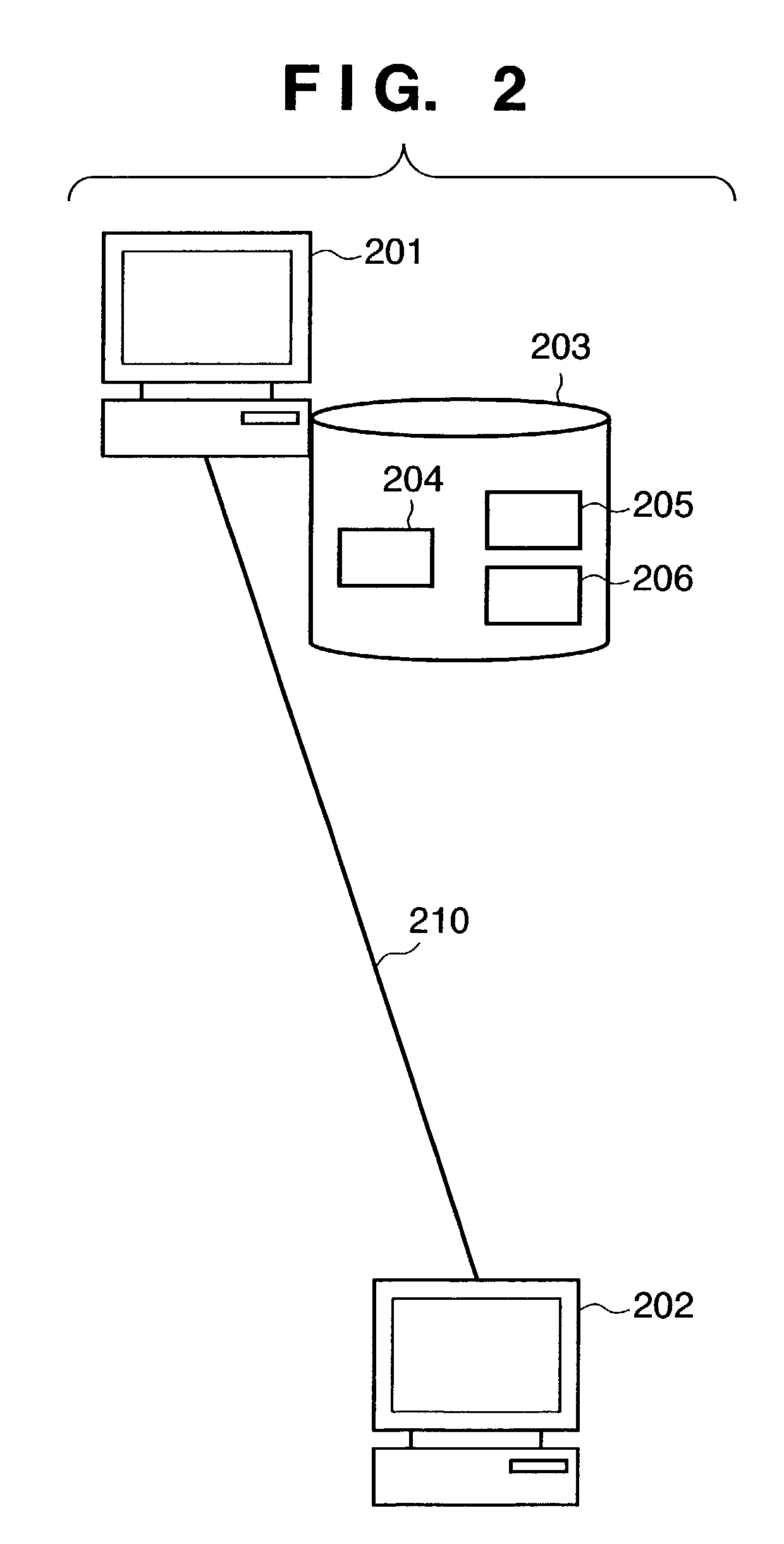
[0202]In the following description, only differences from the first embodiment will be explained. In the first embodiment, the user operates the image communication apparatus 202 to start processing by using the acquisition of HTML data from the image communication apparatus 201 as a trigger. However, the user can also operate the image communication apparatus 201 and transmit HTML data designated by the user to the image communication apparatus 202, thereby starting processing by using this transmission as a trigger.

[0203]FIG. 14 is a flow chart showing a data transmission process in an image communication apparatus 201. The user operates an input unit 101 of the image communication apparatus 201 to select HTML data to be transmitted to an image communication apparatus 202 (step S1401). As the method of selection, a file list may be displayed ...

third embodiment

[0208]The third embodiment according to the present invention will be described in detail below with reference to the accompanying drawings.

[0209]In the following description, only differences from the first and second embodiments will be explained. In the first and second embodiments, only regions necessary for layout are acquired. However, a system according to the third embodiment need not be so designed. In addition, although segmentation is performed such that the number of segmented regions is minimized in the first and second embodiments, the system according to the third embodiment need not be so designed.

[0210]For example, a well-known Flashpix image format (“Flashpix Specification 1.0”, I3A) can hold an image having the same contents at a plurality of resolutions. In addition, each resolution image can be held as it is segmented into tiles each having 64×64 pixels, and partial image data can be accessed for each tile.

[0211]FIG. 16 is a view showing tile segmentation in the...


PUM


Abstract

A client apparatus checks overlap of graphic objects described in multimedia description data. For an image found to be not overlapped with another graphic object, the client apparatus transmits a whole image request for whole image data to a server apparatus. For an image found to be overlapped with another graphic object, the client apparatus determines one or more partial images, and transmits a partial image data request corresponding to each determined partial image. The client apparatus receives the whole image data or partial image data returned from the server apparatus in response to the request, and generates a layout image described by the multimedia description data by using the received whole image data or partial image data.

Description

FIELD OF THE INVENTION[0001]The present invention relates to multimedia description data containing external reference to image data, and a technique of communicating image data to be referred to by the multimedia description data.BACKGROUND OF THE INVENTION[0002]HTML (Hyper Text Markup Language) mainly used in the World Wide Web system is text data made up of tags surrounded by “<” and “>” and character data. This HTML allows description of multimedia documents containing texts and image data, and has been widely used and developed with the spread of the Internet.[0003]The initial HTML simply laid out text data and image data in the display area of a display program called a browser. With the spread after that, however, the HTML has been extended to express more complicated layouts. This extension is presently organized as style sheets by W3C (World Wide Web Consortium). For example, style sheet standards such as CSS (Cascade Style Sheet) and XSL (Extensible Stylesheet Langua...

Claims


Application Information

Patent Timeline
Patent Type & Authority Patents(United States)
IPC IPC(8): G06K9/60G06F3/153H04L29/06H04L29/08H04N1/387H04N7/14
CPCH04L29/06H04N21/8153H04L67/04H04N21/4728H04L29/06027H04L69/329H04L9/40H04L65/1101
Inventor FUKUDA, YASUO
Owner CANON KK
Learn More