Monitoring of call information in a wireless location system

a wireless location and call information technology, applied in the field of wireless transmitter locating methods and apparatuses, can solve the problems of reducing the efficiency of wireless location and reducing the difficulty of wireless location for most approaches to function properly, and saving enormous costs

Inactive Publication Date: 2007-01-23
TRUE POSITION INC
View PDF66 Cites 258 Cited by
  • Summary
  • Abstract
  • Description
  • Claims
  • Application Information

AI Technical Summary

Benefits of technology

[0474]The true scope the present invention is not limited to the presently preferred embodiments disclosed herein. For example, the foregoing disclosure of a presently preferred embodiment of a Wireless Location System uses explanatory terms, such as Signal Collection System (SCS), TDOA Location Processor (TLP), Applications Processor (AP), and the like, which should not be construed so as to limit the scope of protection of the following claims, or to otherwise imply that the inventive aspects of the system are limited to the particular methods and apparatus disclosed. Moreover, as will be understood by those skilled in the art, many of the inventive aspects disclosed herein may be applied in location systems that are not based on TDOA techniques. For example, the processes by which the Wireless Location System determines TDOA and FDOA values can be applied to non-TDOA systems. Similarly, the invention is not limited to systems employing SCS's constructed as described above, nor to systems employing AP's meeting all of the particulars described above. The SCS's, TLP's and AP's are, in essence, programmable data collection and processing devices that could take a variety of forms without departing from the inventive concepts disclosed herein. Given the rapidly declining cost of digital signal processing and other processing functions, it is easily possible, for example, to transfer the processing for a particular function from one of the functional elements (such as the TLP) described herein to another functional element (such as the SCS or AP) without changing the inventive operation of the system. In many cases, the place of implementation (i.e., the functional element) described herein is merely a designer's preference and not a hard requirement. Accordingly, except as they may be expressly so limited, the scope of protection of the following claims is not intended to be limited to the specific embodiments described above.

Problems solved by technology

The location of wireless E9-1-1 callers will save response time, save lives, and save enormous costs because of reduced use of emergency responses resources.
This careful power control leads to a situation known to those skilled in the art as the near-far problem, which makes wireless location difficult for most approaches to function properly.

Method used


Image

  • Monitoring of call information in a wireless location system
  • Monitoring of call information in a wireless location system
  • Monitoring of call information in a wireless location system

Examples


Embodiment Construction

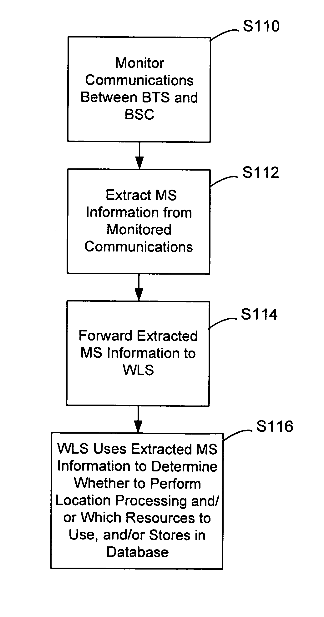
[0056]A goal of the present invention is to provide a mechanism for non-invasively collecting information concerning cell, frequency, and caller for purposes of directing a wireless location system. For example, the present invention provides a method that may be used in a Wireless Location System of the kind described below to locate GSM mobile phones. With the architecture described below, the system would not be required to detect and demodulate messages from the mobile terminal during call setup. Instead, the WLS could ascertain call setup information from the interface between the BTS and the BSC, which is commonly called the “Abis” interface. From the Abis interface, the location system can identify the calling party (indirectly), the called party (i.e., 911), and the TDMA / FDMA resource being used for a given call at any time.

[0057]The following is a description of an illustrative WLS of the kind in which the present invention may be used. This description is intended to provi...


PUM


Abstract

In an overlay Wireless Location System, an Abis interface is monitored to obtain information used to locate GSM phones. Signaling links of the Abis interface are passively monitored to obtain certain information, such as control and traffic channel assignment, called number, and mobile identification, which is not available from the GSM air interface of the reverse channel. This approach also applies to IDEN and can include CDMA systems where the GSM architecture has been used and the system includes a separated BTS to BSC interface.

Description

CROSS REFERENCE TO RELATED APPLICATIONS[0001]This is a continuation of U.S. patent application Ser. No. 09 / 909,221, filed Jul. 18, 2001, now U.S. Pat. No. 6,782,264 B2, Aug. 24, 2002, “Monitoring of Call Information in a Wireless Location System,” which is a continuation-in-part of U.S. patent application Ser. No. 09 / 539,352, filed Mar. 31, 2000, now U.S. Pat. No. 6,317,604 B1, Nov. 13, 2001, “Centralized Database for a Wireless Location System,” which is a continuation of U.S. patent application Ser. No. 09 / 227,764, filed Jan. 8, 1999, now U.S. Pat. No. 6,184,829 B1, Feb. 6, 2001, “Calibration for Wireless Location System.”FIELD OF THE INVENTION[0002]The present invention relates generally to methods and apparatus for locating wireless transmitters, such as those used in analog or digital cellular systems, personal communications systems (PCS), enhanced specialized mobile radios (ESMRs), and other types of wireless communications systems. More particularly, the present invention re...

Claims


Application Information

Patent Timeline
Patent Type & Authority Patents(United States)
IPC IPC(8): H04Q7/20G01S19/03G01S1/02G01S5/02G01S5/06H04W4/90H04W64/00
CPCG01S5/02G01S5/021H04W64/00G01S5/06G01S1/026H04W76/007H04W4/22H04W24/00H04W76/50H04W4/90G01S5/01G01S2205/06
Inventor ANDERSON, ROBERT J.
Owner TRUE POSITION INC
Why Eureka
Try Eureka