Wind energy turbine

a technology of wind energy turbine and turbine blade, which is applied in the direction of machines/engines, mechanical devices, mechanical devices, etc., can solve the problems of increasing difficulty in effective cooling of the above-mentioned components and difficulty in feeding enough air into the tower for sufficient cooling of the components

Active Publication Date: 2007-01-30
GENERAL ELECTRIC CO
View PDF4 Cites 197 Cited by
  • Summary
  • Abstract
  • Description
  • Claims
  • Application Information

AI Technical Summary

Problems solved by technology

Due to the increased performance of modern wind energy turbines, effective cooling of the above-mentioned components is increasingly difficult.
However, in particular with...

Method used


Image

  • Wind energy turbine
  • Wind energy turbine
  • Wind energy turbine

Examples


Embodiment Construction

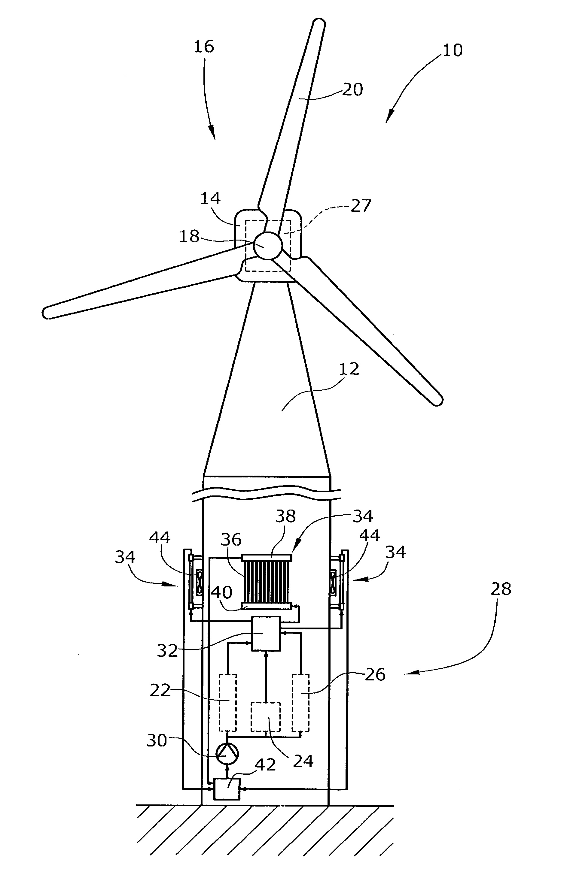
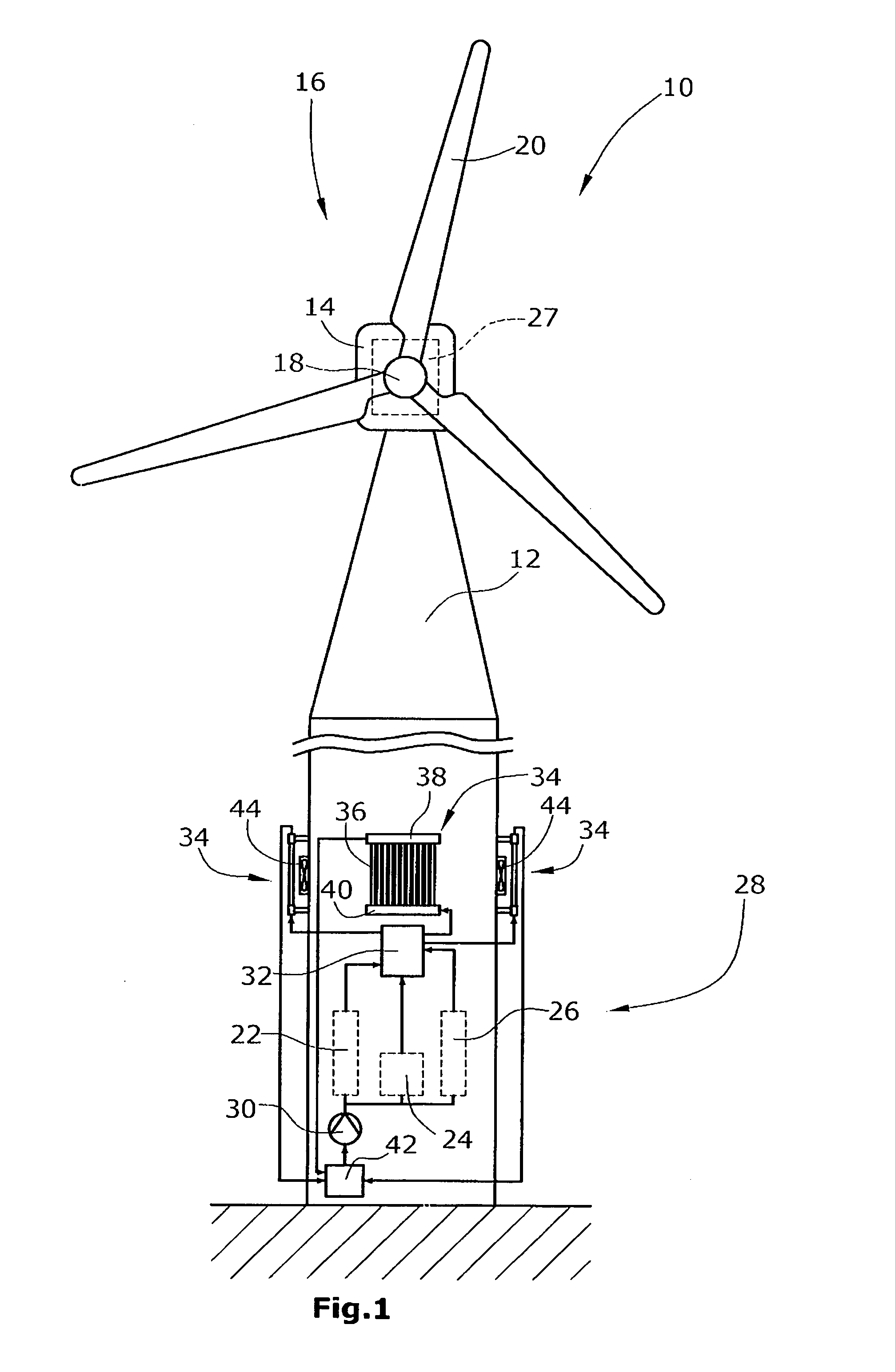
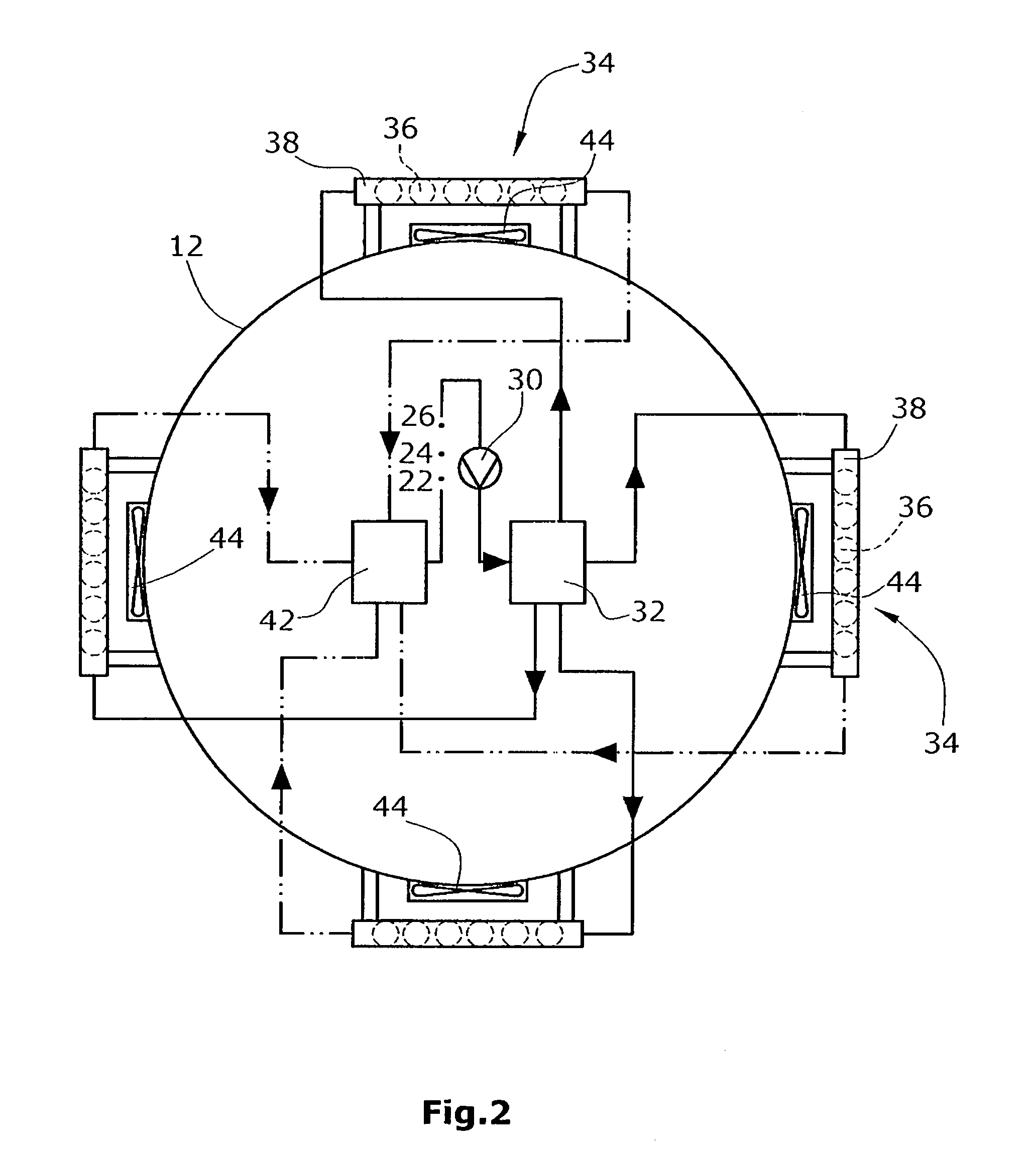
[0009]The present invention involves a cooling circuit for a wind energy turbine built as an open loop, partially closed loop, or a completely closed loop. A cooling medium (gas or liquid) flows through the cooling circuit from the at least one unit to be cooled to at least one heat exchanger or cooling element for cooling down the cooling medium. According to one embodiment of the invention, at least one heat exchanger is located outside of the wind energy turbine and, in particular, on an outer side of the tower and / or nacelle of the wind energy turbine so that it can be cooled by ambient air and wind.

[0010]In one embodiment, the cooling components are used in a closed loop cooling circuit with a cooling medium provided as a cooling liquid, e.g. water. The unit or component to be cooled is cooled by the cooling liquid flowing through the unit or component or parts thereof and downstream of the unit or component through at least one heat exchanger located on the outer side of the t...


PUM


Abstract

A wind energy turbine includes a tower, a nacelle rotatably supported by the tower, a rotor rotatably supported by the nacelle, and at least one unit to be cooled and arranged in the tower and/or the nacelle. The unit is adapted to be cooled by a cooling medium flowing in a cooling circuit from the unit to at least one heat exchanger. The at least one heat exchanger is located outside of the tower and/or nacelle and configured to be cooled by ambient air.

Description

BACKGROUND OF THE INVENTION[0001]This invention relates generally to a wind energy turbine having at least one unit or component to be cooled, and, in particular, to cooling at least one component or unit of a wind energy turbine using a cooling fluid.[0002]A wind energy turbine comprises several mechanical and electrical components which generate heat energy losses during their operation. These components or units include, for example, a gear box (if provided) and a generator. Both of these are typically arranged in the nacelle rotatably supported by a tower. The components also include a converter and a transformer, both of which are typically located within the tower and are utilized to feed electrical energy converted from the mechanical energy of the rotor via the generator into the grid. In addition, the components include controllers for controlling operation of the wind energy turbine. The controllers are typically arranged within the tower. Due to the increased performance ...

Claims


Application Information

Patent Timeline
IPC IPC(8): F01K27/00
CPCF03D9/002F03D11/00Y02E10/725Y02E10/722F05B2260/20F03D9/25F03D80/60Y02E10/72
Inventor JANSSEN, WILHELM
Owner GENERAL ELECTRIC CO
Why Eureka
Try Eureka