Grinding tool for a grinder with rotary oscillating drive

a technology of rotating oscillating drive and grinding tool, which is applied in the direction of grinding/polishing hand tools, grinding machines, grinding/polishing apparatus, etc., can solve the problems of unsuitability of known grinders, and achieve the effect of avoiding strong vibration of grinding tools and increasing removal ra

Inactive Publication Date: 2007-01-30
C & E FEIN GMBH & CO KG
View PDF22 Cites 46 Cited by
  • Summary
  • Abstract
  • Description
  • Claims
  • Application Information

AI Technical Summary

Benefits of technology

[0011]It is a third object of the invention to disclose a grinder having a rotating oscillatory drive which allows for a grinding along longitudinal edges with a high removal rate.
[0017]The elastic design of the grinding pad negates vibrations and pushes resulting from the straight design of the grinding surface. Thus with such a grinder numerous grinding operations along longitudinal profiles can be performed. Herein the cross-section of the grinding pad can be adapted to the particular shape of the surface profile to be ground. Thus, a higher removal rate up to 5-fold when compared with the prior art can be reached.
[0032]In this way a safe mounting and simple assembly on the grinding section is ensured.
[0035]Thus a sanding paper can be fixed to the grinding pad in a particularly simple and fast way.
[0038]Also when using such a design, a simple and fast attachment of a sanding paper to the grinding pad can be reached. Since herein no pivot levers are necessary, by contrast only a clamp serving for securing the sanding paper, a particularly cost-effective design is reached.
[0040]In this way a safe fixation of the sanding paper to the grinding pad is ensured.

Problems solved by technology

For such a grinding the known grinder is not suitable.
However this grinding tool is not driven rotatingly oscillating about a fixed output shaft, but is oscillated back and forth in a longitudinal direction.

Method used


Image

  • Grinding tool for a grinder with rotary oscillating drive
  • Grinding tool for a grinder with rotary oscillating drive
  • Grinding tool for a grinder with rotary oscillating drive

Examples


Embodiment Construction

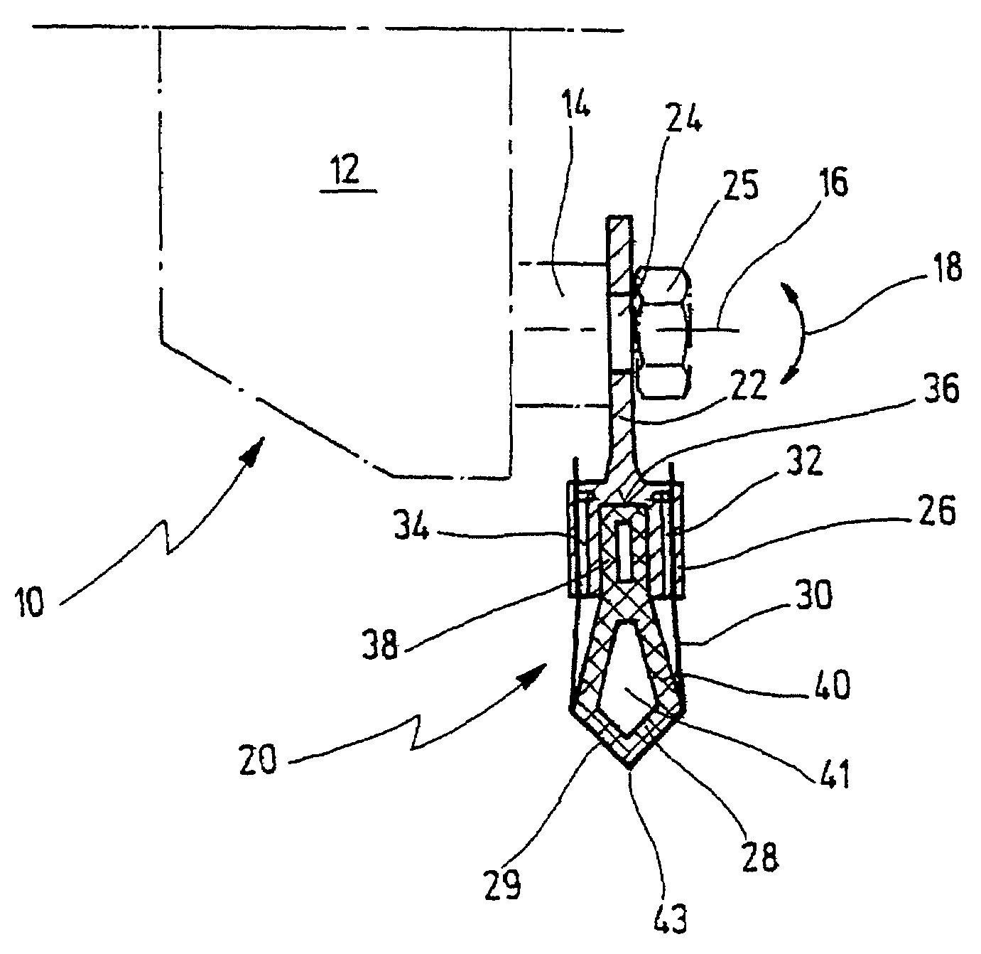
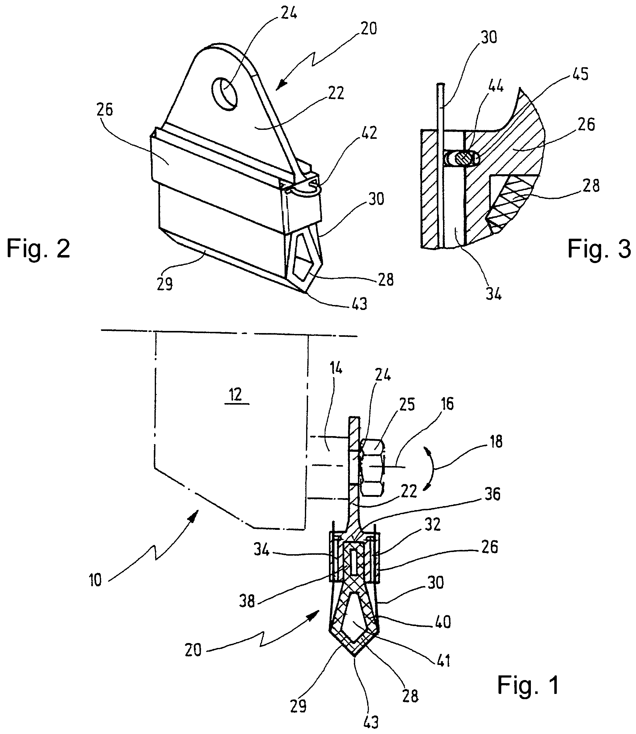
[0052]A first embodiment of the grinder according to the invention is shown in FIG. 1 and depicted in total with numeral 10. The grinder 10 comprises a rotary oscillating drive 12, merely depicted schematically with numeral 12, which oscillatingly drives an output shaft 14 about its longitudinal axis 16 with a small pivot angle between about 0.5 and 7° and at a high frequency between about 5000 and 25000 oscillations per minute (cf. double arrow 18).

[0053]On the output shaft 14 a support for mounting a grinding tool 20 is provided which, e.g., may be configured simply as a threaded blind hole by means of which the grinding tool 20 is affixed using a screw 25 extending through a mounting opening 24 of the grinding tool 20.

[0054]It will be understood that any kind of support may be provided for connecting the grinding tool 20 with the output shaft 14. For instance, also positively shaped supports may be used, such as by means of a hexagon or the like.

[0055]In FIG. 1 the grinding tool ...


PUM


Abstract

Disclosed is a grinding tool for a grinder comprising a rotary oscillating drive, the output shaft of which is driven so as to oscillate back and forth about its longitudinal axis and is configured for securing the grinding tool thereon. The grinding tool comprises a grinding pad which is made of a resilient material and encompasses at least one grinding surface that runs straight in one direction of extension and parallel to a tangent to the output shaft of the rotary oscillating drive.

Description

RELATED APPLICATIONS[0001]This application is a continuation application of co-pending International Patent Application PCT / EP2003 / 014278 filed on Dec. 16, 2003 which designates the United States and claims priority of German patent application 103 08 600.5 filed on Feb. 27, 2003 and being fully incorporated by reference herewith.BACKGROUND OF THE INVENTION[0002]The invention relates to a grinding tool for a grinder comprising a rotary oscillating drive, the output shaft of which is oscillatingly driven about its longitudinal axis and comprises a support for mounting the grinding tool thereon, wherein the grinding tool comprises a receptacle configured for connecting with the support of the grinder for grinding in an operating position.[0003]Such a grinder is known from EP-B-0 244 465.[0004]The known grinder comprisese a rotary oscillating drive the output shaft of which is oscillatingly driven about its longitudinal axis at high frequency and with a small pivot angle. To the output...

Claims


Application Information

Patent Timeline
Patent Type & Authority Patents(United States)
IPC IPC(8): B24B7/00B24B23/00B24B27/08B24B23/02B24B23/04B24B29/06
CPCB24B23/02B24B29/06B24B23/04
Inventor SCHUMACHER, HERMANN
Owner C & E FEIN GMBH & CO KG
Why Eureka
Try Eureka