Magnetic anchor remote guidance system
a technology of magnetic anchors and guidance systems, which is applied in the field of magnetic anchor remote guidance systems and magnetic anchor guide apparatuses, can solve the problems of inability to raise the diseased portion using forceps, inability to provide a portion to be cut, etc., to achieve quick and easy operation
- Summary
- Abstract
- Description
- Claims
- Application Information
AI Technical Summary
Benefits of technology
Problems solved by technology
Method used
Image
Examples
first embodiment
(A) First Embodiment
(I) Structure of Magnetic Anchor Remote Guidance System
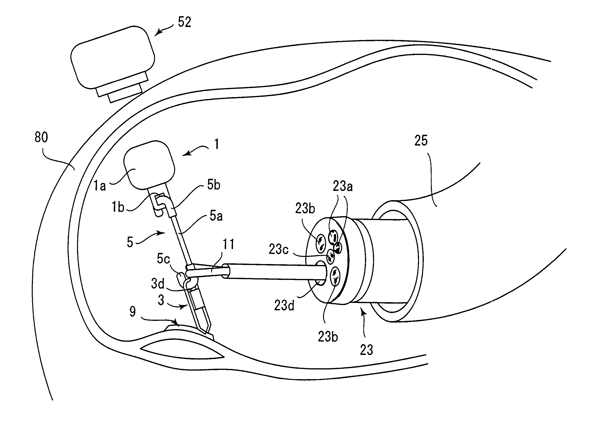
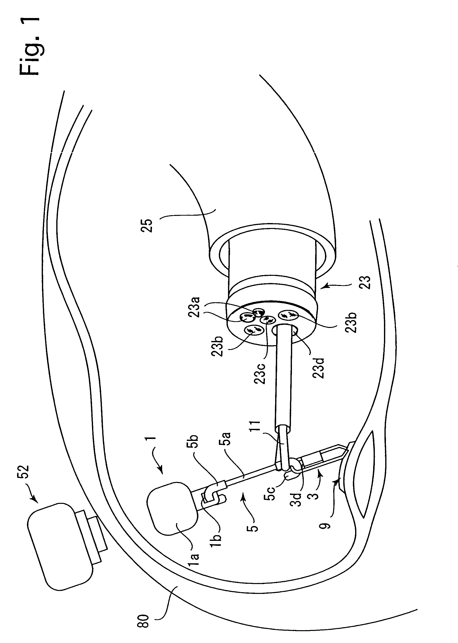
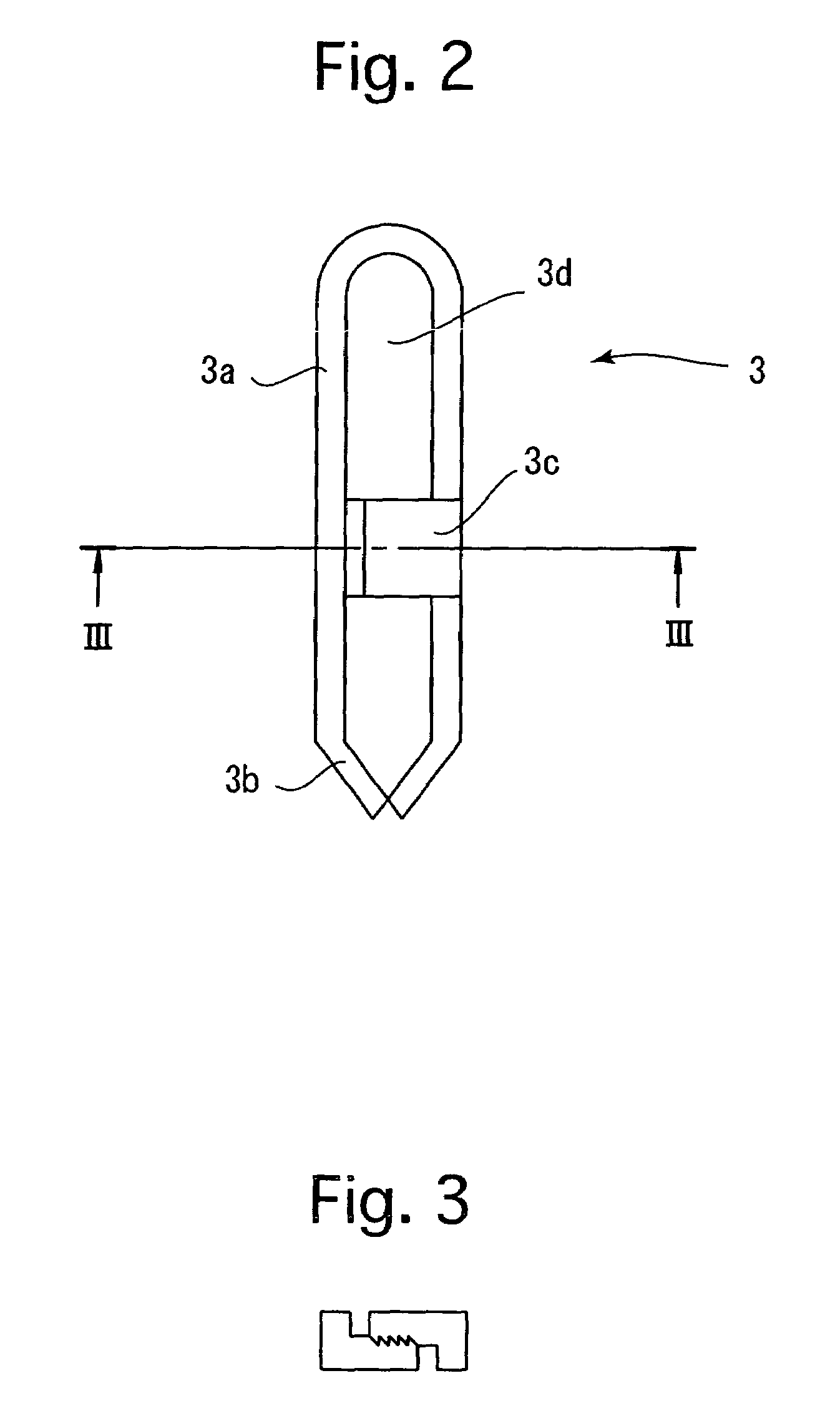
[0050]FIGS. 1 through 3 show the main elements (magnetic anchor 1, clip 3, and connector 5) of a magnetic anchor remote guidance system which are inserted in a patient's body. FIGS. 4 and 5 show a magnetic anchor guide apparatus 50 which attracts and controls (powers) the magnetic anchor 1 from the outside of the patient's body. FIGS. 6 through 10 show a magnetic anchor remote guidance system which is used to resect a diseased portion of a patient by way of example.
[0051]The magnetic anchor 1 includes a generally cylindrical ferromagnetic main body 1a which is provided on one surface thereof with a hole 1b. The ferromagnetic main body 1a can be a magnet made of, for example, fine iron or iron alloy, a platinum magnet, a rare-earth magnet, or a magnet made of terbium-disprosium-iron alloy, etc.
[0052]The clip 3 shown in FIGS. 2 and 3 defines an engagement member which is adapted to hold and raise a diseased por...
second embodiment
(B) Second Embodiment
[0072]FIGS. 12A through 12C show a relationship of the magnetic anchor 1, the connector 5, the clip 3 and the guide sheath 35 according to the second embodiment of the present invention. Note that in the second embodiment, the elements corresponding to those in the first embodiment are designated with like reference numerals.
[0073]In the second embodiment, the magnetic anchor 1, the connector 5, and the clip 3 are inserted integrally in the patient's body. FIG. 12A shows a position in which the magnetic anchor 1, the connector 5 and the clip 3 are set in the guide sheath 35. FIG. 12B shows a position in which the rear end 35a of the guide sheath 35 has been removed by pulling a cutting string 37 of FIG. 12A. FIG. 12C shows a position in which the magnetic anchor 1, the connector 5 and the clip 3 are forced out of the guide sheath by pushing a flexible pushing rod 39. FIG. 13 shows an outer appearance of the endoscope 41 in which the magnetic anchor 1, the connec...
third embodiment
(C) Third Embodiment
[0078]In the third embodiment of the invention, the magnetic guide member 52 located in front of the patient 80 is supported at the back 52d thereof by an arm 62 which is supported by a main body 60 capable of moving in a plane, as show in FIG. 17. The arm 62 is provided with three articulated joints 64 so that the arm 62 is rotatable at the articulated joints in the longitudinal direction of the arm. The rotatable magnetic guide member 52 can be moved to an optional position on the front side of the patient 80 by moving the main body 60 and independently adjusting the rotational angle of the arm at the articulated joints 64. The remaining structure, other operations and effects of the third embodiment are the same as those of the first embodiment. The number and position of the articulated joints 64 are optional. The direction of the movement of the arm at the articulated joints is not limited to the longitudinal direction of the arm and is optional. Moreover, t...
PUM
 Abstract
Description
Claims
Application Information
 - R&D
- Intellectual Property
- Life Sciences
- Materials
- Tech Scout
- Unparalleled Data Quality
- Higher Quality Content
- 60% Fewer Hallucinations
Browse by: Latest US Patents, China's latest patents, Technical Efficacy Thesaurus, Application Domain, Technology Topic, Popular Technical Reports.
© 2025 PatSnap. All rights reserved.Legal|Privacy policy|Modern Slavery Act Transparency Statement|Sitemap|About US| Contact US: help@patsnap.com


