Sealing sleeve for sealing residual limb in a prosthetic socket

a residual limb and sealing technology, applied in the field of sealing sleeves for sealing residual limbs, can solve the problems of comparatively large prestressing force, collapsed retention force, and loss of retention, and achieve good air tight sealing

Inactive Publication Date: 2007-01-30
KAUPTHING BANK
View PDF71 Cites 98 Cited by
  • Summary
  • Abstract
  • Description
  • Claims
  • Application Information

AI Technical Summary

Benefits of technology

[0014]Based on the above state of the art, it is the objective of the present invention to create a prosthetic socket or a sealing sleeve which will assure good air tight sealing between a residual limb and a prosthetic socket without requiring more than slight prestressing forces.

Problems solved by technology

On the other hand, the force of retention collapses immediately when air enters any gap between the residual limb and the prosthetic socket.
In the known design, the pressure gradient at the lip seal is in a direction that causes lifting of the lip seal from the residual limb, thereby permitting air to enter the annular gap and, because of the ensuing loss of suction, retention is lost.
It has been observed that a comparatively large prestressing force is required, which in turn may entail interference with blood circulation in the region between the sealing lip and the distal end of the residual limb.

Method used


Image

  • Sealing sleeve for sealing residual limb in a prosthetic socket
  • Sealing sleeve for sealing residual limb in a prosthetic socket
  • Sealing sleeve for sealing residual limb in a prosthetic socket

Examples


Embodiment Construction

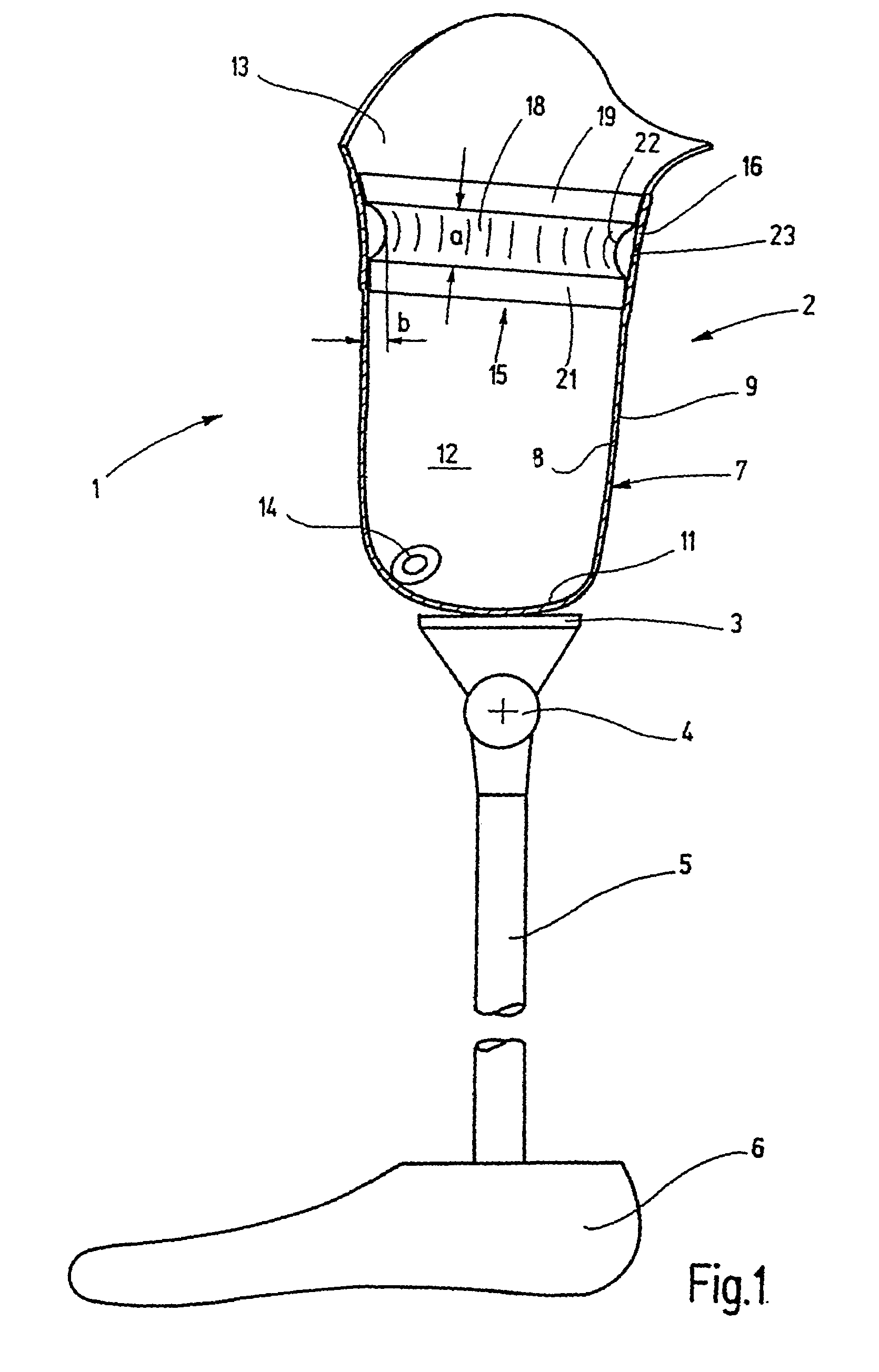
[0037]In a highly diagrammatic manner, FIG. 1 shows an exemplary above-the-knee prosthesis 1 of the invention. The prosthesis 1 comprises a prosthetic socket 2 connected by an adapter 3 to an artificial knee joint 4. An artificial lower-leg having a foot 6 is connected to the artificial knee joint 4.

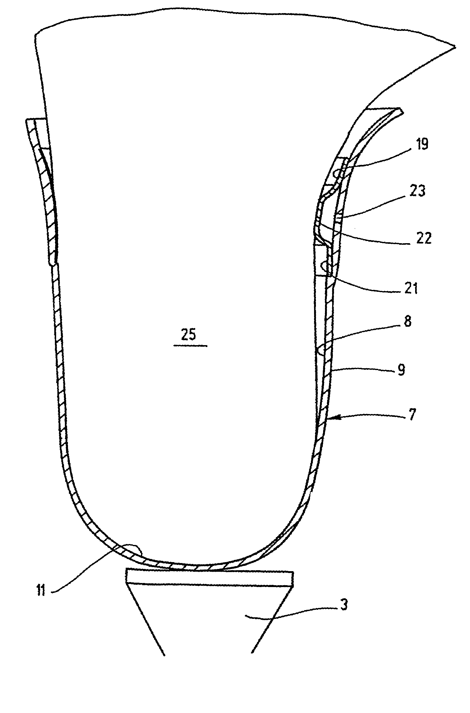
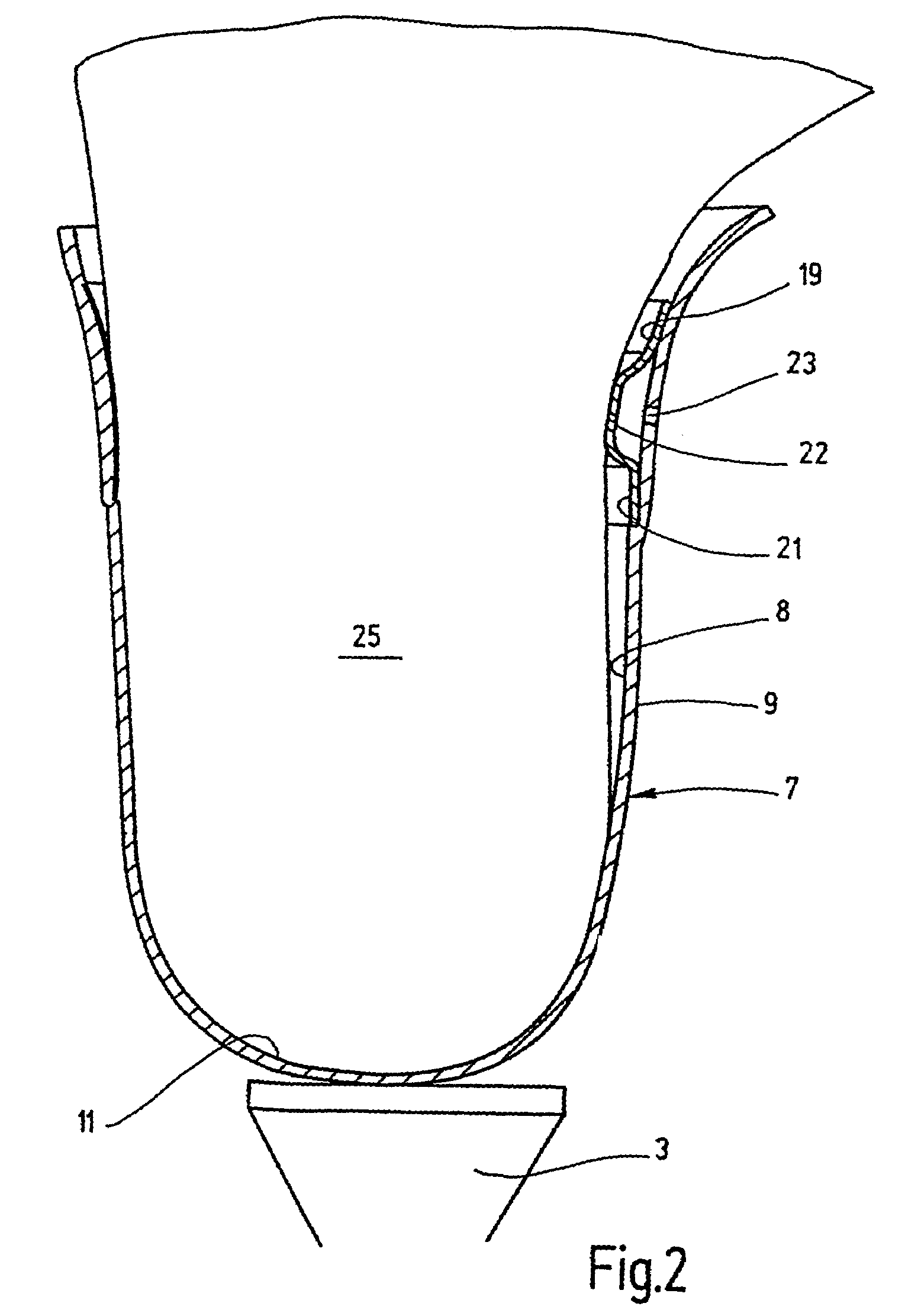
[0038]The prosthetic socket 2 is composed of a socket wall 7 having an inner wall 8 and an outer wall 9 and a socket distal end 11. The socket distal end 11 merges integrally into the socket wall 7 at the lower end of the wall. Jointly with the inner socket wall 8, the socket distal end 11 subtends a substantially cup-shaped inner volume 12 which is accessible through a proximal residual limb insertion opening at the proximal end. The length of the inside volume 12 and its shape depend on the kind of residual limb and the kind of prosthetic treatment involved. The specific nature of the inside volume 12 is not otherwise significant.

[0039]The prosthetic socket 2 is a so-called suction-soc...


PUM


Abstract

A prosthetic socket is fitted at a distance from its distal end with an annular chamber. This annular chamber is closed by a contour-conforming sealing wall facing the inner side of the prosthetic socket, said wall being designed to hermetically rest against the outer side of a residual limb. The space between the contour-conforming wall and the hard prosthetic socket is vented to atmosphere, whereby self-enhancing compression by the sealing wall against a residual limb arises when a partial vacuum arises in the distal prosthetic socket between the wall and the distal end. A liner having a sealing wall also is disclosed.

Description

[0001]This application is a national stage filing of PCT / DE02 / 03085 having a filing date of 23 Aug. 2002, which has the benefit of priority of DE 101 42 492.2 filed 30 Aug. 2001.BACKGROUND[0002]A. Field of the Invention[0003]This invention relates to sealing sleeves for sealing residual limbs in suction retention prosthetic sockets.[0004]B. Related Art[0005]Residual limb are inserted like pistons in cup-shaped prosthetic sockets. It is therefore known to utilize ambient air pressure and partial vacuum to retain a prosthetic socket on a residual limb. The residual limb for this effect must be kept hermetically sealed against the inner prosthetic socket wall or against a liner donned over the residual limb.[0006]When sealing is adequate, a force applied to remove the prosthetic socket from the residual limb will generate a partial vacuum acting against it. On the other hand, the force of retention collapses immediately when air enters any gap between the residual limb and the prosthet...

Claims


Application Information

Patent Timeline
Patent Type & Authority Patents(United States)
IPC IPC(8): A61F2/80A61F2/78A61F2/60A61F2/42A61F2/00
CPCA61F2/80A61F2/7843A61F2250/0069A61F2002/805
Inventor CARSTENS, FELIX
Owner KAUPTHING BANK
Why Eureka
Try Eureka