Multiphase nanocomposite material and method for its manufacture
a nanocomposite material and multi-phase technology, applied in the field of synthetic materials, can solve the problems of low cost, rapid method, and easy scalable
- Summary
- Abstract
- Description
- Claims
- Application Information
AI Technical Summary
Problems solved by technology
Method used
Image
Examples
example 1
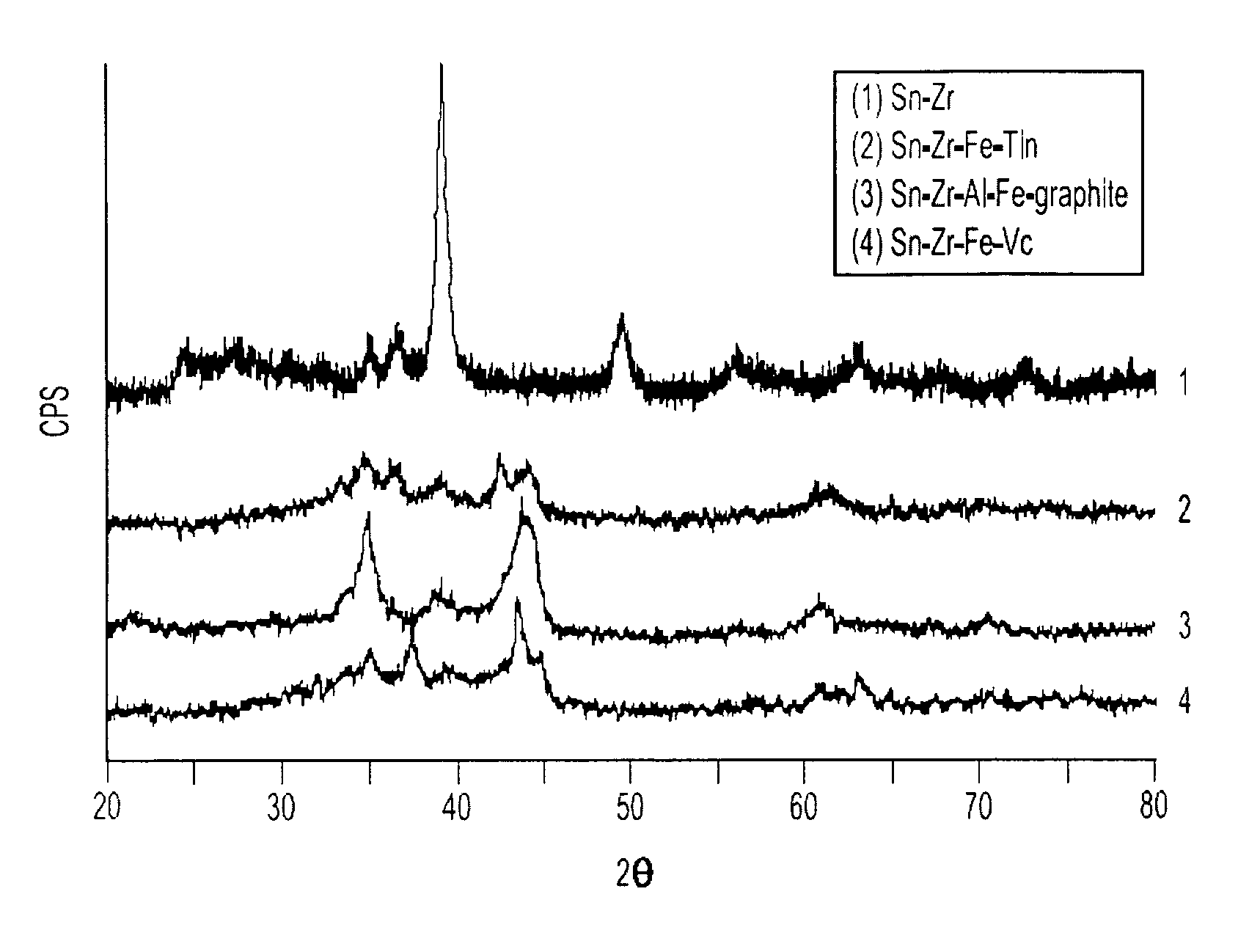
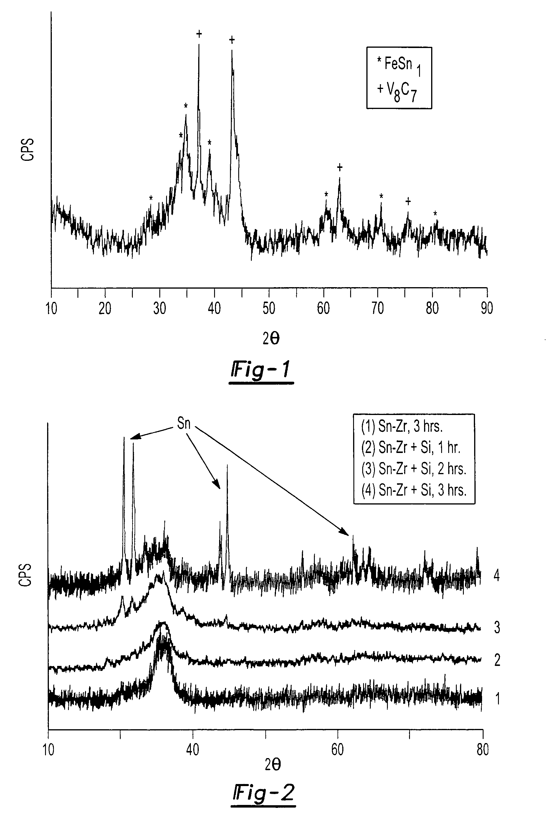
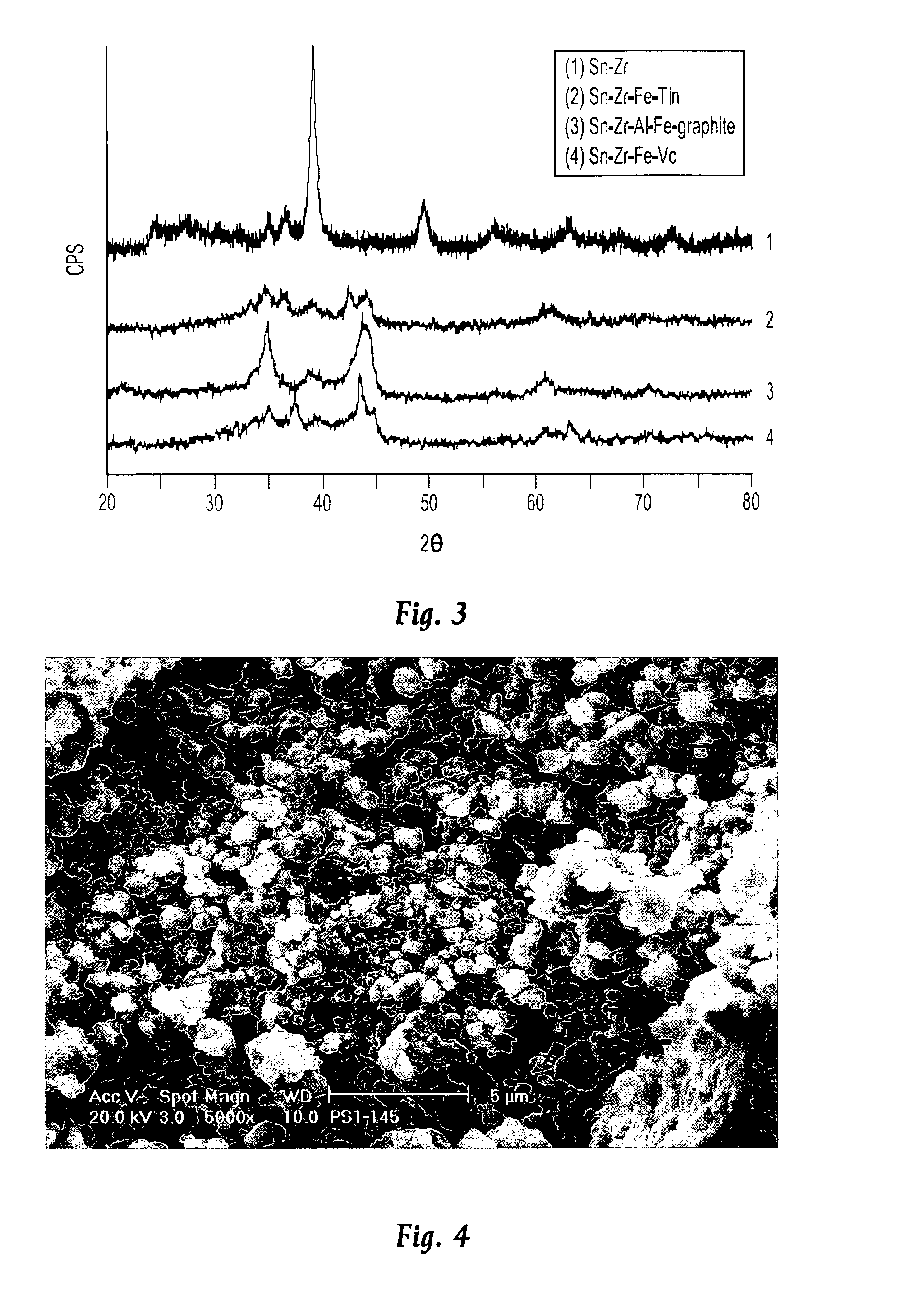
[0025]In a first experimental series, a multiphase nanocomposite material of the present invention having the composition Sn4Zr2Fe4(VC)5 was prepared by a ball milling process in which all of the components of the material were simultaneously processed. The process was carried out a number of times and in each instance, a 10 gram batch of starting material was prepared from 3.97 g Sn (Cerac, −325 mesh), 1.526 g Zr (Cerac, 3–5 micron) 1.896 g Fe (Cerac, −325 mesh) and 26.9 g VC (Cerac, −325 mesh). These materials were thoroughly mixed inside an Ar-filled glove box to a uniform color and texture, after which they were loaded into a hardened steel vial together with alumina milling balls. The mass ratio of balls to material is in the approximate range of 1.5–2:1, and it has been found that the balls may be either 12 millimeters or 6 millimeters in diameter. The vial cap was placed onto the vial and tightened by hand, after which the vials were removed from the glove box and loaded into...
example 2
[0027]While in the foregoing example, all of the ingredients of the composition were charged into the mill at one time, the various components could be incorporated in stages. As such, inactive amorphous or crystalline alloys may be formed prior to the addition of the active components. Such a process will have the advantage of minimizing the consumption / solubility of the active phase in an inactive alloy such as FeSn2. For example, it is anticipated that Zr and Fe could be milled together to form an alloy such as FeZr2 or Fe2Zr, prior to the addition of Sn or Si. An extension of this concept would be to include Fe, Zr and VC to form an inactive composite prior to adding the active component. Upon addition of the active component, the materials would be further milled to produce the desired nanocomposite structure. Preferably, between stages, the samples are handled such that exposure to air is minimized, as for example by the use of a glove box.
example 3
[0028]This example refers to substitutional staged alloying of components, and in this example, as in Example 2, the starting components of the material can be added at different times to control the microstructure of the resulting product. This example differs conceptually from Example 2 in that the active component is initially incorporated into the material during the first milling stage. In the second stage, a component is added that will preferentially substitute for the active component in the first stage alloy due to enhanced thermodynamic stability. The active component from the stage one alloy can then be extruded to the grain boundaries of the material or recrystallized during the milling process. This behavior has been observed and confirmed under actual experimental conditions, and the best example of this behavior was observed in the Sn—Zr—Si system. In this experiment, a 2 gram batch of material comprising Sn and Zr was initially milled for three hours in a ball mill, ...
PUM
| Property | Measurement | Unit |
|---|---|---|
| size | aaaaa | aaaaa |
| size | aaaaa | aaaaa |
| crystallite size | aaaaa | aaaaa |
Abstract
Description
Claims
Application Information
 - R&D
- Intellectual Property
- Life Sciences
- Materials
- Tech Scout
- Unparalleled Data Quality
- Higher Quality Content
- 60% Fewer Hallucinations
Browse by: Latest US Patents, China's latest patents, Technical Efficacy Thesaurus, Application Domain, Technology Topic, Popular Technical Reports.
© 2025 PatSnap. All rights reserved.Legal|Privacy policy|Modern Slavery Act Transparency Statement|Sitemap|About US| Contact US: help@patsnap.com


