Device and method for measuring angles

a technology of angle measurement and measuring device, which is applied in the direction of galvano-magnetic hall-effect devices, instruments, galvano-magnetic devices, etc., can solve the problems of limiting the accuracy of the system, polarization or tooth pitch errors, eccentricities, etc., and achieve the effect of reducing the error caused by tolerances

Inactive Publication Date: 2007-01-30
ROBERT BOSCH GMBH
View PDF14 Cites 10 Cited by
  • Summary
  • Abstract
  • Description
  • Claims
  • Application Information

AI Technical Summary

Benefits of technology

[0006]By the provision according to the invention of a number of sensors, and the averaging of the signals obtained, based on the individual sensor signals, the effects of the aforementioned tolerances on the measurement accuracy can be reduced in a highly effective way.
[0007]In a preferred embodiment of the device of the invention, three sensors are provided, which are distributed about the at least one transducer wheel. Sensors arranged at 120° angles from one another form an ideal compromise between the lowest possible number of sensors and the functional capability of the device. Moreover, there are advantages from symmetry in terms of production tolerances. However, it should be emphasized that the method of the invention also functions satisfactorily when only two sensors are used. To further increase the accuracy, however, more than two sensors can also be used.
[0009]In this respect it is advantageous that the first transducer wheel has n segments, and the second transducer wheel has n+1 segments. For instance, n can equal 24, but other values can also be selected, depending on the accuracy to be required. Such an embodiment with two different transducer wheels makes it possible to use so-called Nonius methods, with which especially reliable evaluation of the sensor signals obtained is possible.
[0010]Expediently, the sensors are embodied as Hall sensors. Such Hall sensors can be obtained economically and prove to be robust and reliable in practice.

Problems solved by technology

If an angle measuring system realized with magnetic sensors is based on scanning a transducer wheel that is either itself magnetized or comprising ferromagnetic material and on moving past the scanning sensor distorts the field of a transducer magnet, production tolerances limit the accuracy of the system.
Aspects that are especially problematic are eccentricities, polarization or tooth pitch errors, and nonhomogeneities in the field amplitudes.
Moreover, the scanning sensors cannot be positioned arbitrarily accurately, so that additional positioning tolerances are also involved.
Once again, however, angle errors are caused by the aforementioned tolerances.

Method used


Image

  • Device and method for measuring angles
  • Device and method for measuring angles
  • Device and method for measuring angles

Examples


Embodiment Construction

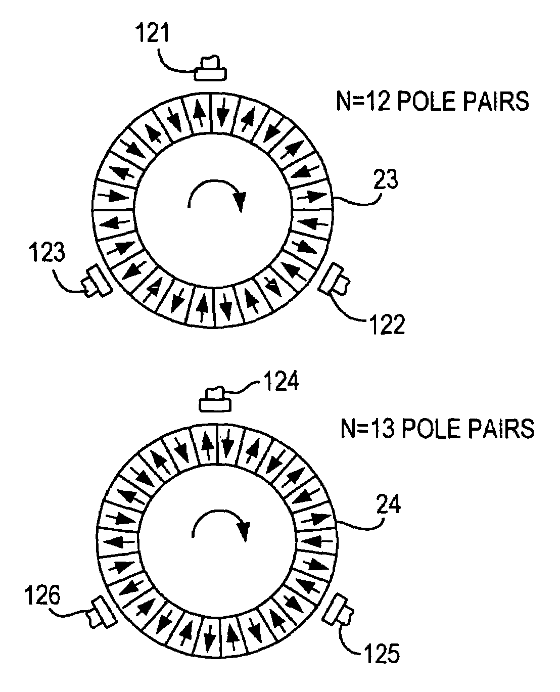
[0023]The drawing description below pertains to the special embodiment of scanning of a magnetic multipole wheel. However, the method can also be attained advantageously with other transducer wheels involving nonmagnetic or magnetic measuring principles. The measured values and measurement errors indicated below refer by way of example to pole wheels with n=12 and n=13 pole pairs, and with an outer diameter of 30.8 mm.

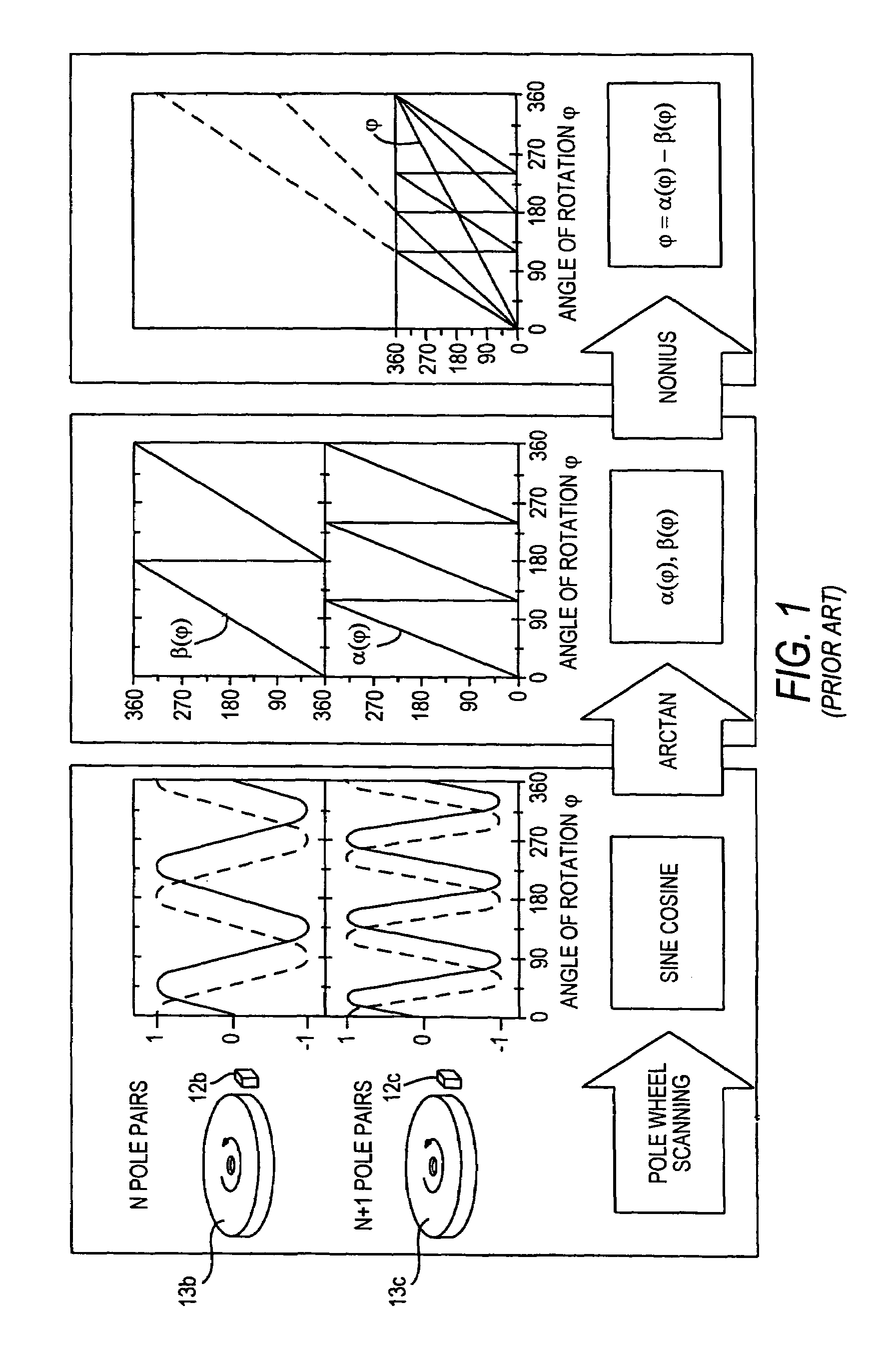
[0024]The measurement principle on which the invention is based will first be explained in conjunction with FIG. 1.

[0025]A steering column is embodied with a torsion bar. Concentrically to the torsion bar, three magnetic multipole wheels are provided. Upon a rotation of the upper part of the steering column relative to the lower part about its longitudinal axis, an angular displacement of the magnetic multipole wheel 13a occurs relative to the remaining magnetic multipole wheels. Disposed next to the multipole wheels is a sensor 12, which has three sensor elements 12a,...


PUM


Abstract

A device for angle measurement, having at least one transducer wheel and at least one sensor, including at least one sensor element and cooperating with the transducer wheel, in which by means of the cooperation of the transducer wheel and the sensor, a pair, which can be associated with an angle to be measured, comprising one sine-wave signal and one cosine-wave signal can be obtained, in which at least two sensors are provided, whose sine-wave signals and cosine-wave signals, for obtaining an averaged sine-wave signal and averaged cosine-wave signal, and / or after the formation of an arc tangent signal from the respective averaged or unaveraged sine-wave signals or cosine-wave signals, can be put computationally into relation with one another by means of an evaluation device in order to obtain an averaged arc tangent signal.

Description

BACKGROUND OF THE INVENTION [0001]The present invention relates to a device for angle measurement and to a corresponding method.[0002]The demand for high-precision yet also robust angle measuring systems in the automobile industry is constantly rising. At present, the areas in which angle measuring systems are used include an electronic stability program (ESP) and electrically assisted steering systems. Over the long term, the transition to steer-by-wire will increase the demand for angle measuring systems still further, and this development involves a simultaneous increase in the accuracy demanded.[0003]Magnetic sensors are predestined for use in the automobile, because of their contactless, robust measurement principle. If an angle measuring system realized with magnetic sensors is based on scanning a transducer wheel that is either itself magnetized or comprising ferromagnetic material and on moving past the scanning sensor distorts the field of a transducer magnet, production to...

Claims


Application Information

Patent Timeline
Patent Type & Authority Patents(United States)
IPC IPC(8): G01B7/30G01D5/14G01D5/16G01D5/244G01D5/245
CPCG01D5/145G01D5/24409G01D5/2497G01D5/2452G01D5/24476G01B7/30
Inventor HAAS, GUNTHERSIEGLE, HENRIKMOENIKES, RALF
Owner ROBERT BOSCH GMBH
Why Eureka
Try Eureka