Wiper-type phase shifter with cantilever shoe and dual-polarization antenna with commonly driven phase shifters

a phase shifter and cantilever shoe technology, applied in the field of wireless base station antenna systems, can solve the problems of affecting the performance of the phase shifter, the type of phase shifter can experience failure, and the design objective of meeting these competing design objectives is particularly challenging, so as to avoid complicated linkage elements, avoid the effect of complex stress and dimensional changes

Inactive Publication Date: 2007-01-30
ANDREW CORP
View PDF9 Cites 62 Cited by
  • Summary
  • Abstract
  • Description
  • Claims
  • Application Information

AI Technical Summary

Benefits of technology

[0009]The present invention meets the needs described above in an antenna suitable for use as a wireless base station antenna that includes a wiper-type phase shifter with a cantilever shoe that ensures that the electrical contact on the wiper arm remains in electrical communication with the transmission trace located on the antenna backplane without relying to an element, such as a spring-loaded set screw, that passes through the backplane. The cantilever shoe thus provides a wiper hold-down mechanism without requiring holes or slots through the backplane, which could allow rain or other elements to get inside the antenna enclosure. The cantilever shoe is also a small, light weight, low maintenance, and inexpensive wiper arm hold-down mechanism in comparison to larger, bulkier, more complex, and more expensive hold-down mechanism employed previously. In addition, locating a motor for driving the wiper arm on the rear of the backplane opposite the location of the wiper arm advantageously avoids complicated linkage elements.
[0013]Electrical communication between the transmission media on the backplane and the trace contact wiper arm can be direct, such that a direct current (DC) can flow between the elements. Alternatively, this connection may be capacitively coupled, such that only a varying signal can flow between the elements. In particular, a capacitive insulating layer, such as a low-loss dielectric sheet, can be located between these electrical conductors to prevent the flow of DC signals. This type of insulating layer advantageously suppresses intermodulation signal products that can occur when the conductors are in direct contact with each other. Without this type of insulating layer, a measurable non-linear current-voltage relationship can develop over time due to corrosion and other environmental conditions.
[0014]The phase shifter may be operated manually or mechanically (or both), and it may be controlled locally or remotely (or both). Therefore, the actuator may include a knob for manually pivoting the wiper arm. Alternatively or additionally, the actuator may include a motor for mechanically pivoting the wiper arm. The phase shifter may also include a controller for remotely controlling the motor. Typically, the wiper arm is located on a front side of the backplane and the motor is located on the rear side of the backplane, preferably opposite the location of the wiper arm to minimize the complexity of the linkage between the actuator and wiper arm. The front side may also include radiating elements of an antenna array. The wiper arm may also define a gear section for mechanically linking the wiper to another component, such as a drive gear or another wiper arm. In particular, an antenna may include two phase shifters that each include wiper arms that engage each other in this manner to cause coordinated pivotal movement of the wiper arms. For example, each phase shifter may drive a circuit associated with a polarization of a dual-polarization antenna array.

Problems solved by technology

Meeting these competing design objectives is particularly challenging with respect to the moving parts of the antenna, such as the phase shifters used for beam steering and in variable power dividers, which may also be used for beam steering.
This type of phase shifter can experience failure if the wiper arm loses electrical communication with the transmission media trace.
Because wireless base station antennas are typically deployed outdoors on buildings or towers, they are subject to the variable stresses and dimensional changes induced by temperature changes, vibration and external forces of wind, and other types of environmental conditions and variations over extended periods of time.
These conditions can cause relative dimensional changes to occur between the components of the phase shifter assembly that can result in changes in the degree of wiper contact with the transmission media trace.
Changes in wiper contact, such as partial wiper arm separation, can result in operational performance changes of the antenna.
In extreme cases, complete wiper arm separation can result in operational failure of the antenna.
This approach is very effective at maintaining electrical communication between the wiper arm 4 and the transmission media trace 5, but has the disadvantage of requiring a slot through the backplane 2.
This is a problem because in a typically wireless base station antenna, the backplane serves as an exterior wall intended to keep out the weather elements.
Cutting slots through the backplane can cause water to enter the antenna, which can cause the antenna to short, corrode, and freeze if the temperature drops.
Providing this exterior wall in addition to backplane 2, as well as brackets for supporting the backplane within the enclosure 6, increases the cost and complexity of the antenna.
This type of duplication can be costly, particularly when the phase shifters are motor driven, which is desirable for remotely controlled operation.

Method used


Image

  • Wiper-type phase shifter with cantilever shoe and dual-polarization antenna with commonly driven phase shifters
  • Wiper-type phase shifter with cantilever shoe and dual-polarization antenna with commonly driven phase shifters
  • Wiper-type phase shifter with cantilever shoe and dual-polarization antenna with commonly driven phase shifters

Examples


Embodiment Construction

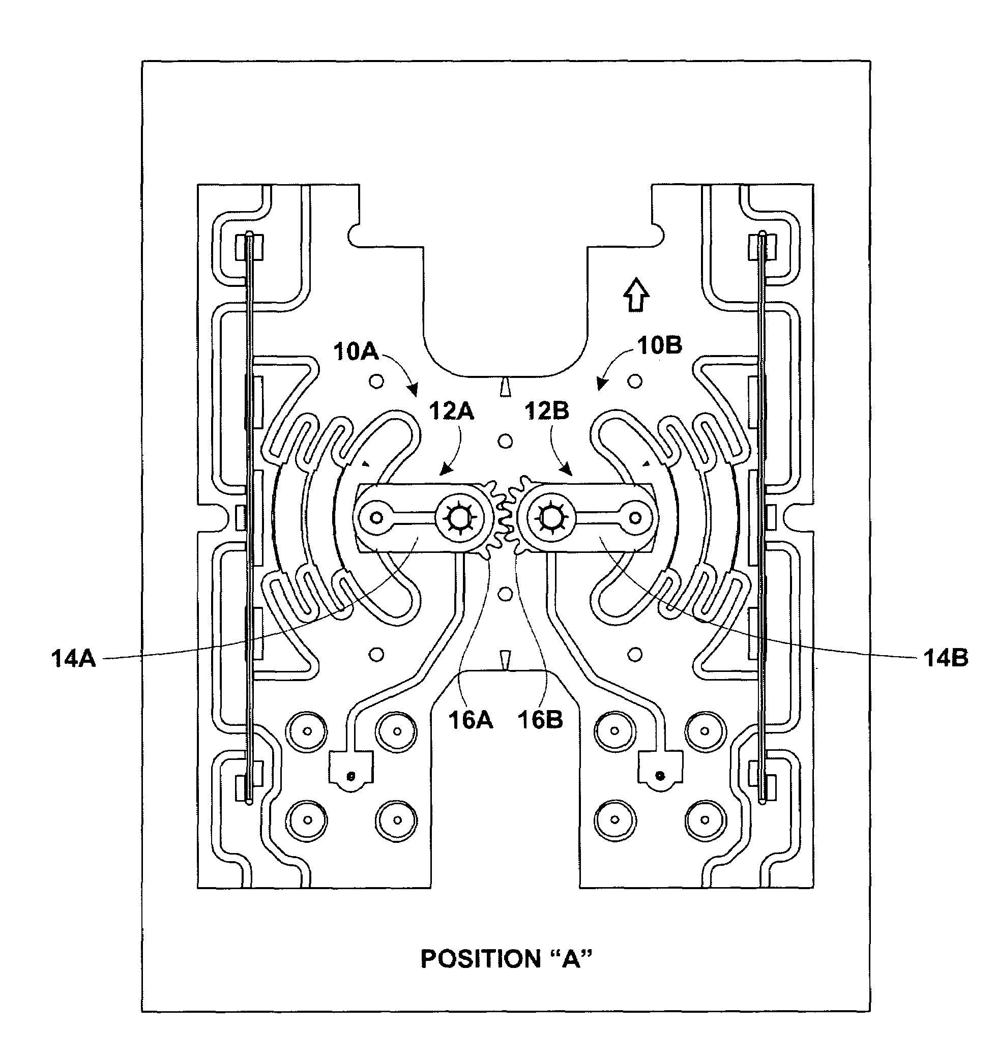
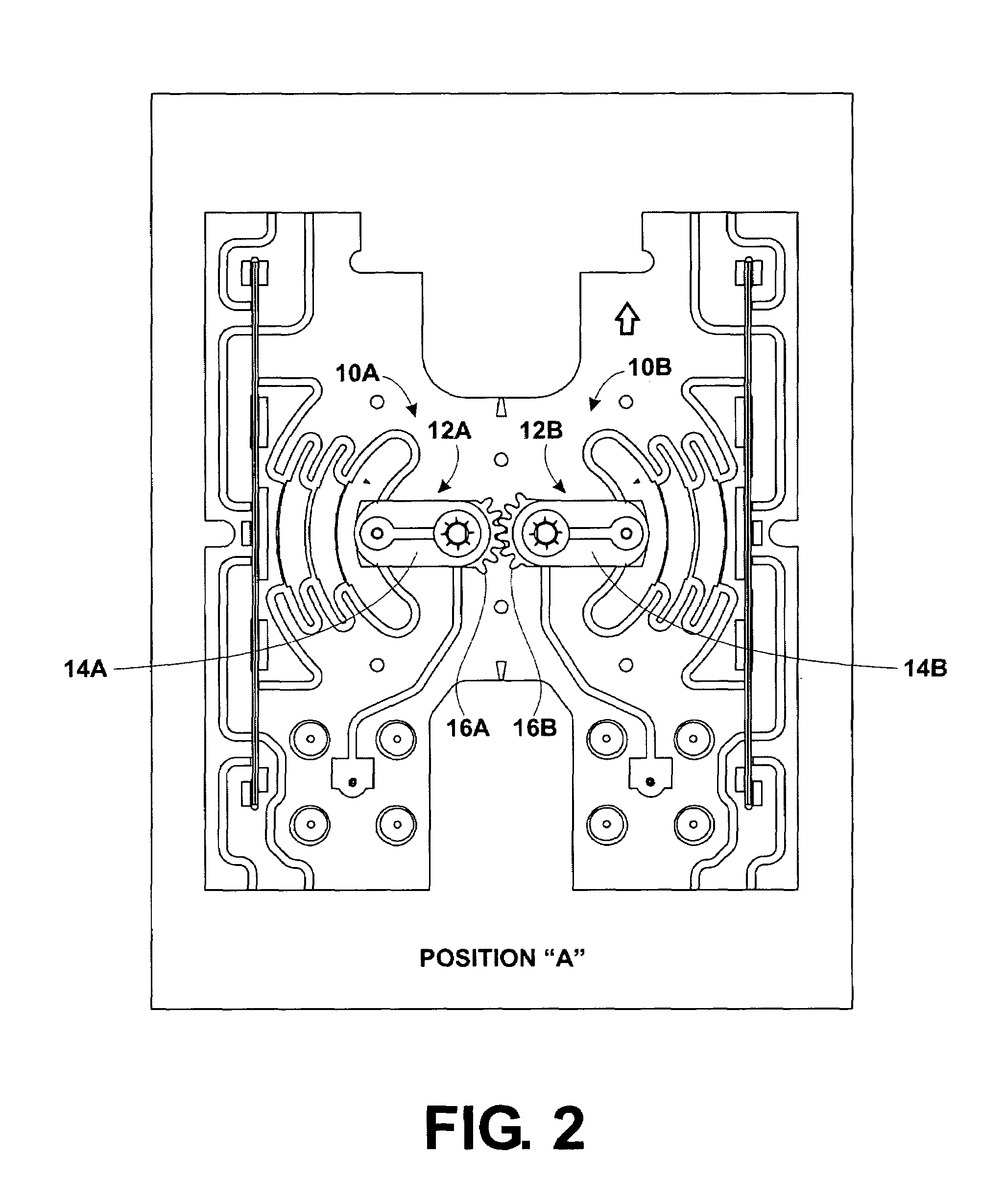
[0041]The present invention may be embodied in a wiper-type phase shifter for an antenna, such as a wireless base station antenna, that includes a cantilever shoe wiper arm hold-down mechanism. In particular, this type of phase shifter may be used to drive a beam steering circuit that controls the direction of a beam formed by the antenna, as in a vertical electrical downtilt antenna. However, the phase shifter may also be used to control beam steering in azimuth or any other desired direction. In addition, the phase shifter may also be used to drive systems other than beam forming and beam steering circuits, such as power dividers, analog amplifiers, beam shaping circuits, and any other circuit employing an analog phase shifter.

[0042]The present invention may also be embodied in a dual-polarization antenna including commonly-driven wiper-type phase shifters. In particular, the wiper arms of the dual-polarization antenna are mechanically linked to each other through gear faces cut d...


PUM


Abstract

A wiper-type phase shifter with a cantilever shoe that ensures that the electrical contact on the wiper arm remains in electrical communication with the transmission trace located on the antenna backplane without relying to an element, such as a spring-loaded set screw, that passes through the backplane. The cantilever shoe thus provides a wiper hold-down mechanism without requiring holes or slots through the backplane, which could allow rain or other elements to get inside the antenna enclosure. A dual-polarization antenna that includes a wiper-type phase shifter for each polarization. The wiper arms define gear portions that engage each other, which allows a single actuator, typically located on the rear of the backplane opposite the location of the wiper arms, to drive both wiper arms in a coordinated manner. The antenna is suitable for use as a wireless base station antenna.

Description

REFERENCE TO RELATED APPLICATIONS[0001]This application incorporates by reference the disclosures of commonly owned U.S. patent application Ser. No. 10 / 290,838 entitled “Variable Power Divider” filed on Nov. 8, 2002; U.S. patent application Ser. No. 10 / 226,641 entitled “Microstrip Phase Shifter” filed on Aug. 23, 2002; U.S. patent application Ser. No. 10 / 623,379 entitled “Vertical Electrical Downtilt Antenna” filed on Jul. 18, 2003; and U.S. patent application Ser. No. 10 / 623,382 entitled “Double-Sided, Edge-Mounted Stripline Signal Processing Modules And Modular Network” filed on Jul. 18, 2003.TECHNICAL FIELD[0002]The present invention relates to wireless base station antennas systems and, more particularly, relates to a wiper-type phase shifter with a cantilever shoe and a dual-polarization antenna including commonly driven phase shifters.BACKGROUND OF THE INVENTION[0003]The present invention represents an improvement over the phase shifters described in commonly owned U.S. patent...

Claims


Application Information

Patent Timeline
Patent Type & Authority Patents(United States)
IPC IPC(8): H01Q3/02H01P1/20
CPCH01P1/184
Inventor JANOSCHKA, DARIN M.
Owner ANDREW CORP
Why Eureka
Try Eureka