Masonry connectors and twist-on hook and method

a technology of twist-on hooks and masonry connectors, which is applied in the direction of building components, building repairs, structural elements, etc., can solve the problems of affecting the progress of wall construction, and reducing the service life of connectors, so as to achieve the effect of reducing the force of

Inactive Publication Date: 2007-02-06
BRONNER JOSEPH
View PDF26 Cites 48 Cited by
  • Summary
  • Abstract
  • Description
  • Claims
  • Application Information

AI Technical Summary

Benefits of technology

[0036]Still another object of the present invention is to provide a method for anchoring a connector in a wall at multiple points, such that the embedment is maintained even in hollow block wall, and even as the depth of embedment is varying, using mortar only without grouting the cells.
[0037]Another object of the present invention is to provide a connector device which is able to resist more efficiently forces perpendicular to the wall as well as forces that are parallel to the wall.

Problems solved by technology

The grouting is disruptive to the progress of wall construction, and is costly.
The connector embedment is weakened by a cold joint because of the shrinkage of the separately poured portions of grout.
Thus, the connector will resist the applied forces in all situations, even when using a hollow masonry wall, using mortar only and without the need for grouting.2. When the hook end of a prior art connector bar is “T-shaped to engage a slotted channel, it applies non-symmetrical forces on the channel, when in shear, which channel is not efficiently designed for such forces.
Thus, in many cases, even if the short slotted channel accommodates the connector hook, it may not accommodate the additional clearance needed for the beam to deflect freely without bending the connector plate or introducing torsion in the beam.
Many times the slot of the slotted channel falls against the solid wall of the cmu, not allowing the connector embedded in the mortar bed to be engaged.
It is not practical to install the slotted channel on an open web of a truss.4. When the hook end of a prior art connector bar is “J” shaped, it hooks to the flange of a beam, truss or to any other steel member.
This is mostly not the case, since even if designed for, the construction tolerances may cause such differences in those elevations.
It is especially not the case when the steel member is sloped, as it is mostly in the roof.
In addition, this does not allow the steel to deflect freely without bending the connector plate or introducing torsion in the steel.

Method used


Image

  • Masonry connectors and twist-on hook and method
  • Masonry connectors and twist-on hook and method
  • Masonry connectors and twist-on hook and method

Examples


examples

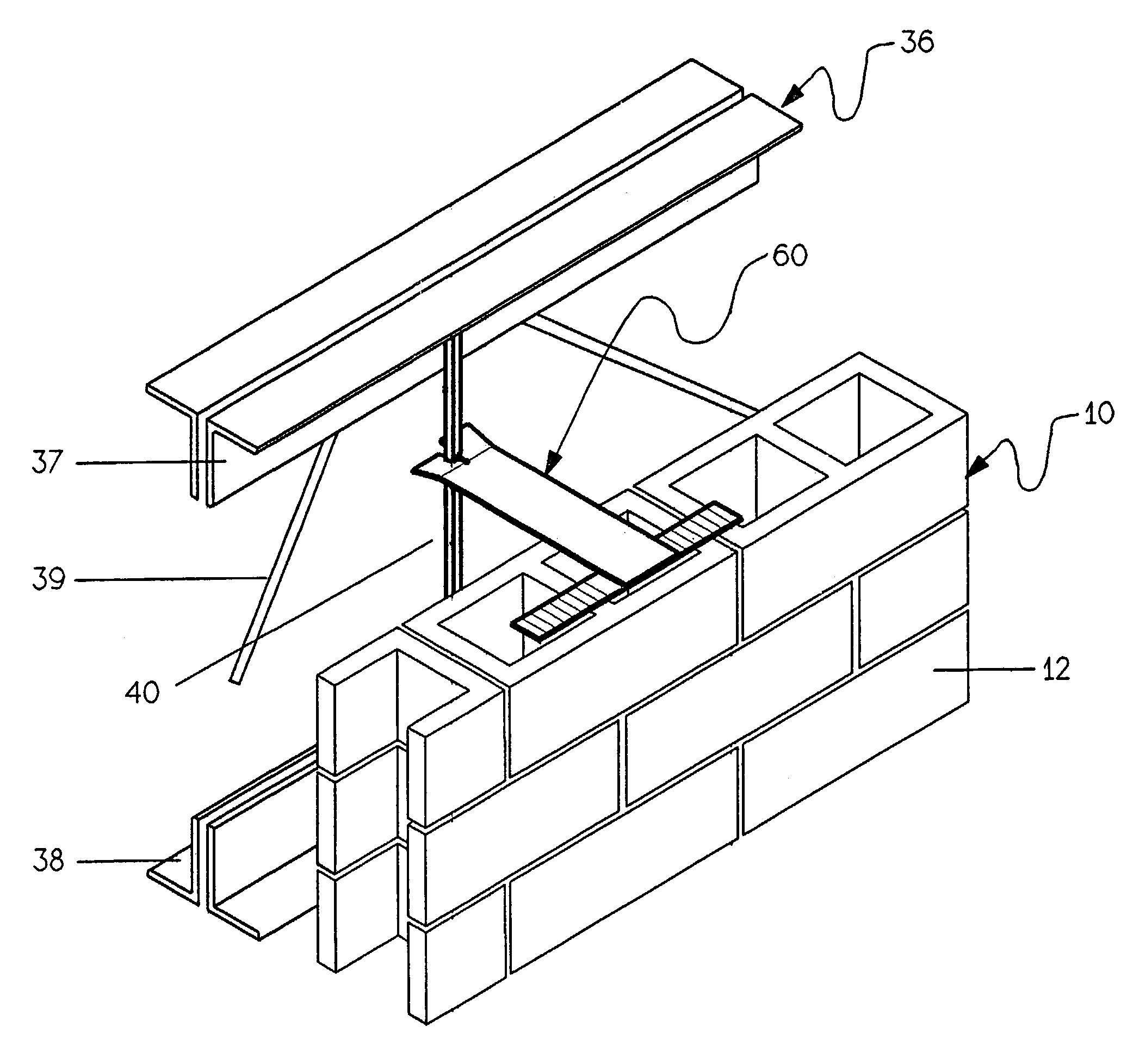
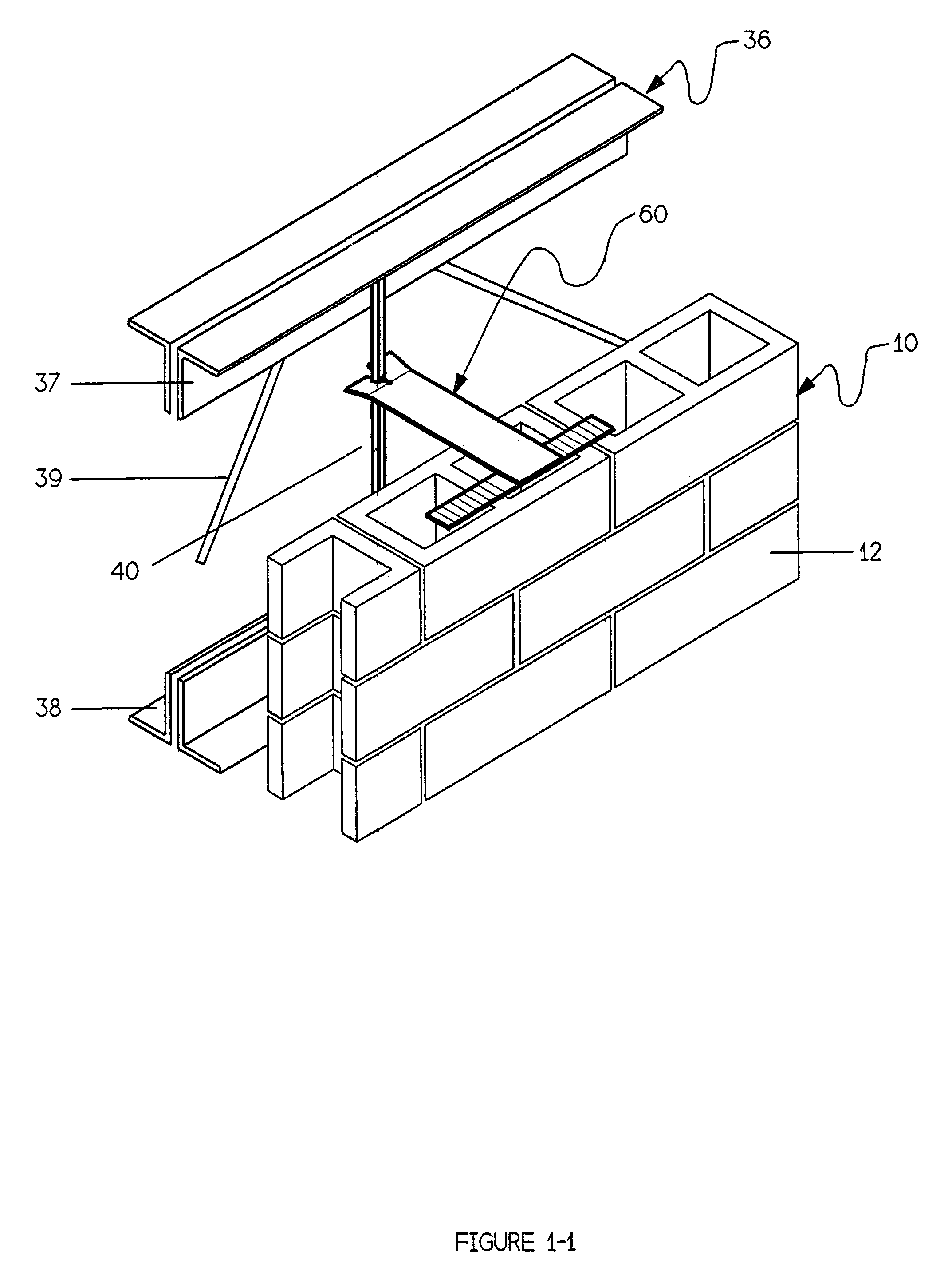
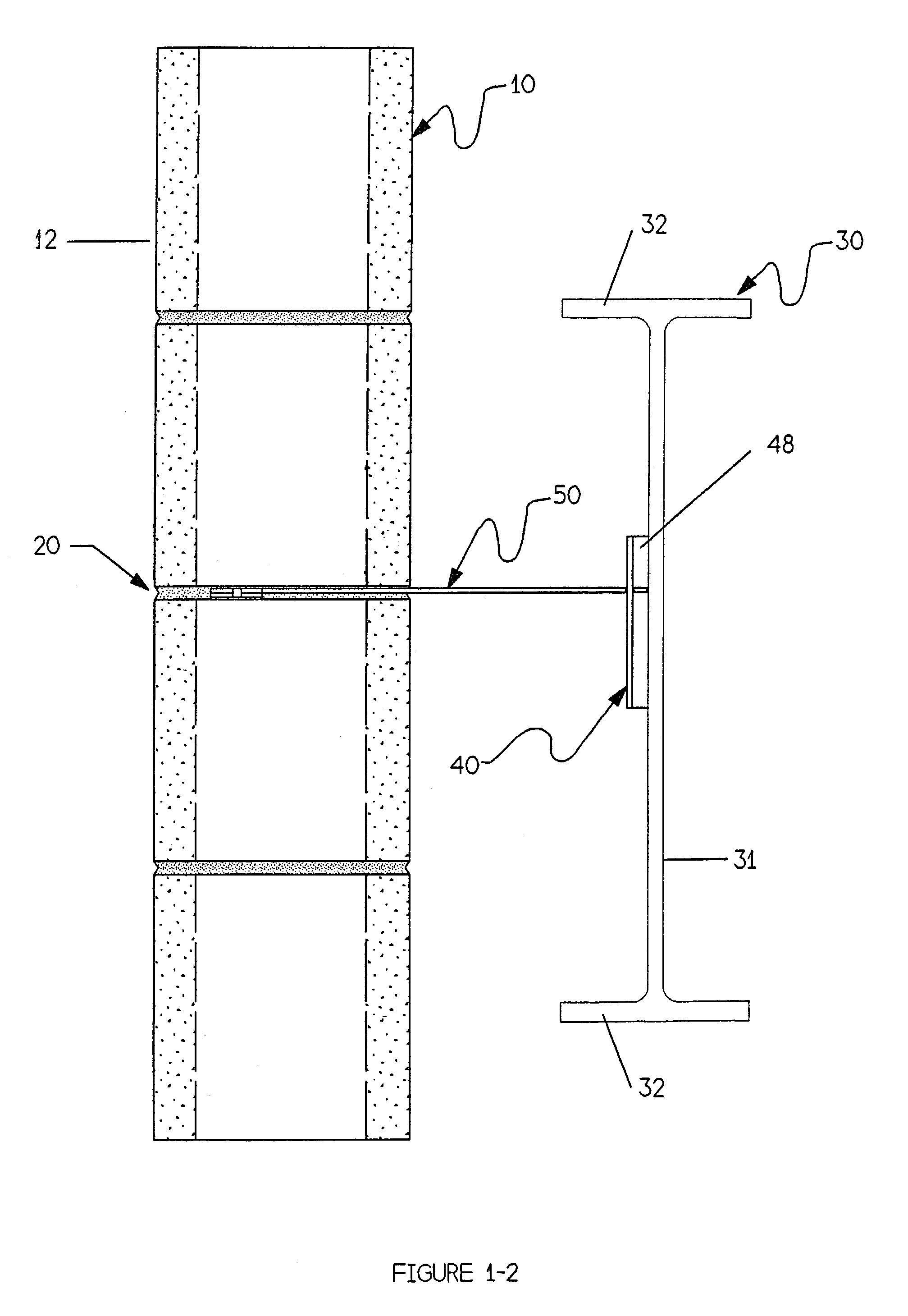
[0125]FIGS. 4-1 through 4-3 demonstrate examples of typical additional uses for embodiments of the present invention.

[0126]FIG. 4-1 illustrates using the “T-Connector” embodiment to join two walls, where the masonry connector of the present invention has several points of attachment with each cmu. FIG. 4-2 further illustrates using this embodiment to connect a masonry wall to a steel beam or truss which has a conventional channel 48.

[0127]The components of the masonry connector embodiments are preferably manufactured from steel plate or bar, which is either cut, bent, or molded to suit the particular embodiment. The steel can be of regular or high strength and can be plain finish, galvanized, stainless steel or any other finish. The hook and anchor bars can be flat or corrugated, they can have straight or serrated edges and punches or dimples, etc. to increase their bond in the mortar bed. The components of the present invention can also be manufactured from other non metallic mater...


PUM


Abstract

A connecting device for joining a wall to a building frame, or for joining walls, comprises a hook member. The frame can comprise steel beams, or also comprise a truss having an open web, and a slide rail attached to the truss' chords in a generally plumb orientation. Embodiments of the hook member substantially encircle one or more slide rails and thereby retain the rails. Other embodiments fit within a channel attached to solid steel webs, or concrete frames. The device's other end is positioned over a course of masonry units, and when embedded in mortar, the cells of the masonry units do not require grouting. Other connecting device embodiments comprise an anchor member securely joined to the member, the connecting device providing multiple points of attachment with the masonry, or multiple members joined to the anchor member. The connecting device can be used for new construction, and in renovations using currently existing steel and concrete frames.

Description

CROSS-REFERENCES TO RELATED APPLICATIONS[0001]This application claims the benefit of U.S. Provisional Patent Applications Ser. Nos.: 60 / 370,532, filed 5 Apr. 2002, and 60 / 374,896, filed 23 Apr. 2002, the contents of which are hereby incorporated by reference.FIELD OF THE INVENTION.[0002]The present invention relates to connecting the walls of a building to the frame of the building. Particularly it relates to a device for, and a method of, connecting a wall constructed from modular units, such as concrete masonry units (“cmu”), bricks, precast concrete elements or any other segments, to the building's frame. The frame can be made of steel, concrete, wood or other materials. The device and method can also be used to connect the walls to each other, for example, at intersections, between adjacent wythes and the like.BACKGROUND OF THE INVENTION[0003]Much of today's building construction consists of a building frame constructed of steel, concrete, or wood, and walls constructed of concr...

Claims


Application Information

Patent Timeline
Patent Type & Authority Patents(United States)
IPC IPC(8): E04B1/16E04B1/41E04C5/02
CPCE04C5/02E04B1/4178
Inventor BRONNER, JOSEPH
Owner BRONNER JOSEPH
Why Eureka
Try Eureka