Defect free composite membranes, method for producing said membranes and use of the same

a composite membrane and membrane technology, applied in the direction of moving filter element filters, filtration separation, separation processes, etc., can solve the problems of weaker membranes, thin membranes, and the polyacrylonitrile based membranes disclosed in u.s. patent no. 4,061,821 are not stable to chlorine attack, and achieve strong physical and chemical binding, strong physical adhesion, and high water permeability

Inactive Publication Date: 2007-02-06
ACCORD PARTNER
View PDF32 Cites 144 Cited by
  • Summary
  • Abstract
  • Description
  • Claims
  • Application Information

AI Technical Summary

Benefits of technology

The present invention relates to a new type of spinneret for making a composite hollow fibre membrane. This spinneret can coat a support with multiple layers simultaneously to create a stronger connection between the membrane and its support. A special coating solution containing a permeable adhesive layer is used to bind the membrane to the support. Additionally, this invention introduces a new approach to controlling the coating quality and adhesion between the membrane and support - regardless of the physical structure of the support. Instead, these factors are independently controlled by simultaneously coating the support with multiple layers. Furthermore, the invention uses ultrasonics in various stages of production to accelerate the process of forming the composite membrane. Overall, this innovation improves efficiency and produces superior membranes compared to previous techniques.

Problems solved by technology

This patent discusses issues related to semiporous membranes used in liquid and gas separations through filtration or dialysis. Specifically, there is a trade-off between membrane permeability and mechanical strength: while a thicker membrane may provide better mechanical strength, its permeability decreases. Additionally, previous methods for coating the membrane onto a supporting braid showed inconsistent results and difficulty controlling the degree of hydroylation. Furthermore, existing techniques for achieving high production rates were limited. Therefore, the technical problem addressed by this patent is how to improve the performance of semipermeable membranes in terms of their mechanical strength and permeability, consistency of manufacturing processes, and ability to achieve high production rates.

Method used


Image

  • Defect free composite membranes, method for producing said membranes and use of the same
  • Defect free composite membranes, method for producing said membranes and use of the same
  • Defect free composite membranes, method for producing said membranes and use of the same

Examples


example 1

Effect of Vacuum Suction, poly(acrylonitrile-co-methacrylonitrile) Particles and Multiple Coatings on Membrane Performance

[0054]All of the chemicals used were purchased from Aldrich Chemicals Inc., Milwaukee, Wis. 53201. A tubular braid used as a membrane support was purchased from Atkins & Pearce Inc. One Braid Way, Covington, Ky. 41017.

[0055]A membrane casting solution (referred to herein as Dope I) was prepared by mixing 12 parts by weight of poly(vinylidene fluoride-co-hexafluropropylene) (PVDF-HFP), 5 parts by weight of poly(acrylonitrile-co-methacrylonitrile), 70 micrometer particles, 4 parts by weight of polyvinylpyrrolidone (PVP), 5 parts by weight of aluminum chloride hexahydrate (AlCl3.6H2O), 2 parts by weight of poly(vinyl butyral-co-vinyl alcohol-vinyl acetate), and 72 parts by weight of 1-methyl-2-pyrrolidinone (NMP).

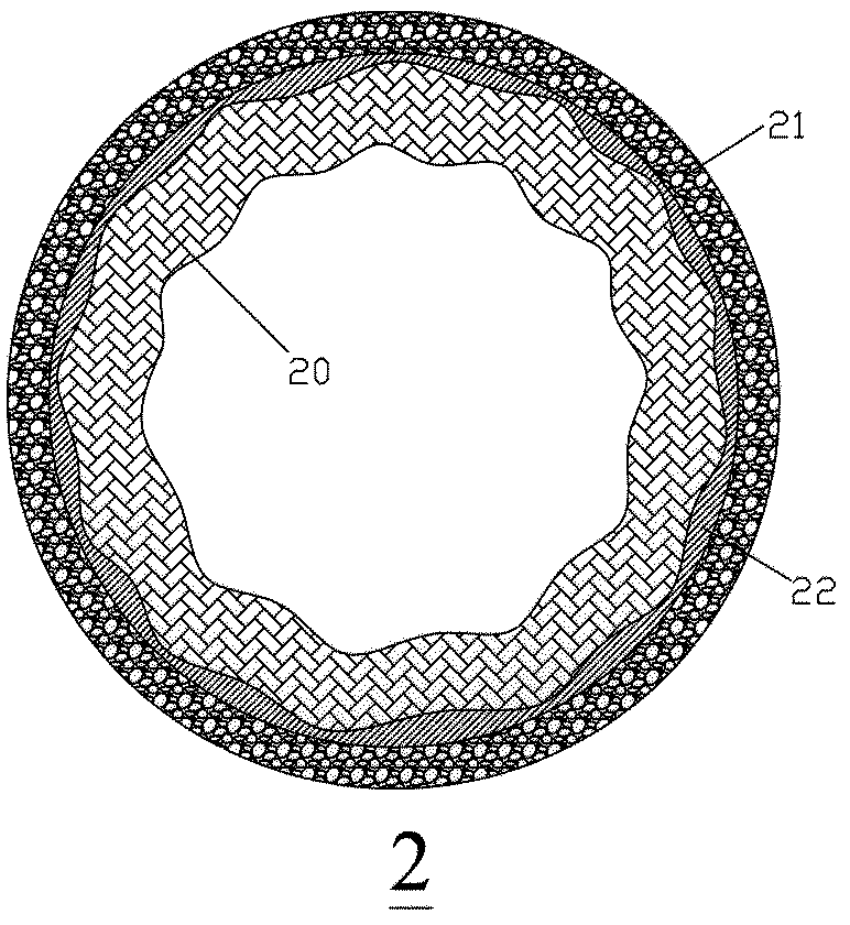
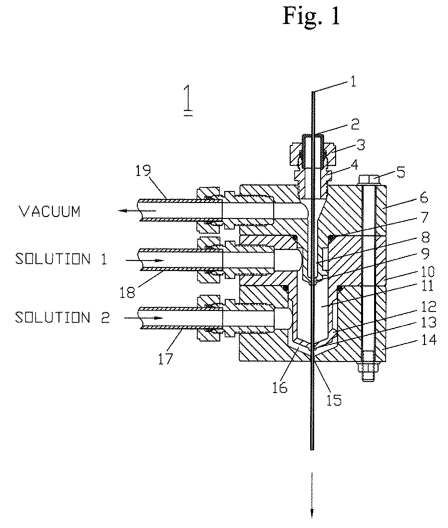
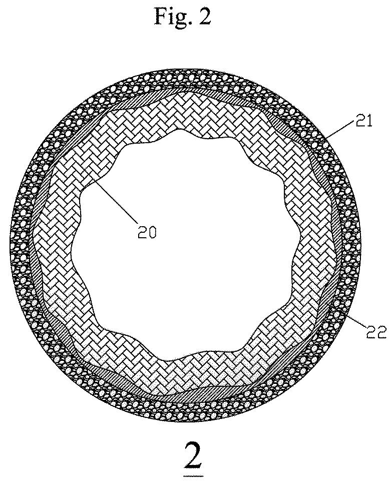
[0056]A composite hollow fiber membrane was prepared by coating a tubular braid purchased from Atkins & Pearce Inc. with Dope I using a spinneret shown in ...

example 2

Effect of Vacuum Suction, Crosslinked PVP Particles, and Multiple Layer Coating on Membrane Performance

[0065]Dope II having a composition given in Table 2 was prepared in the same way as in Example 1. In Example 2, crosslinked PVP particles were used as additives to replace poly(acrylonitrile-co-methacrylonitrile) particles in Example 1. A composite hollow fiber membrane was also prepared in the same way as in Example 1, but at a higher speed of 76 ft / min. The detail conditions used to make the membrane are given in Table 2.

[0066]The composite hollow fiber membrane obtained has an outside diameter of 78 mil, a burst pressure higher than 100 psi, and a water permeability of 35 gfd / psi measured at 10 psi transmembrane pressure.

[0067]A post treatment was carried out by immersing the membrane in a 5,000 ppm sodium hypochlorite solution at ambient temperature for 5 days, the chlorine treated membrane showed a improved pure water permeability of 170 gfd / psi. Surface water obtained from Ca...

example 3

Effect of Both Crosslinked PVP Particles and poly(acrylonitrile-co-methacrylonitrile) Particles on Membrane Performance

[0068]Dope III having a composition given in Table 3 was prepared in the same way as in Example 1. However, both crosslinked PVP particles and poly(acrylonitrile-co-methacrylonitrile) particles were added to increase membrane porosity. A composite hollow fiber membrane was prepared in the same way as in Example 1, but coated at a higher speed of 104 ft / min. The detail conditions used to make the membrane are given in Table 3. The membrane obtained was characterized and the results obtained are summarized in Table 3.

[0069]Although the above illustration and discussion are focused on composite hollow fiber membrane, the formulations, methods and processes discovered in the present invention are applicable to flat sheet composite membranes, large diameter tubular composite membranes and any other composite membrane having a different geometry. Because many possible emb...


PUM

PropertyMeasurementUnit
Fractionaaaaaaaaaa
Pressureaaaaaaaaaa
Percent by massaaaaaaaaaa

Abstract

A defect free semipermeable composite membrane having outstanding integrity and high water permeability is provided. Said composite membrane comprises an inside support layer to provide sufficient mechanical strength, an outside barrier layer to provide selective separation and a middle layer to provide both chemical and physical binding between the support and the barrier layer. Two different methods for making said defect free composite membrane are discovered. These methods have been successfully used to produce high quality coatings and defect free composite membranes, which are independent of chemical composition and physical structure of said support. In the present invention, the ultrasonic sonication is utilized to speed up the phase inversion process of a membrane casting solution, and to produce a composite membrane at a speed higher than that disclosed in the prior art. Said defect free composite membranes have broad applications, ranging from filtration of fruit juice, wine and milk to purification of drinking water, municipal and industrial wastewater.

Description


Claims


Application Information

Patent Timeline
Owner ACCORD PARTNER
Why Eureka
Try Eureka