Systems and methods for providing electric power to mobile and arbitrarily positioned devices

a technology of electric power and control system, applied in the field of systems and methods for providing electric power and/or control system to mobile and arbitrarily placed electromechanical devices, can solve the problem that the electromechanical device is not rendered inoperable, and achieve the effect of reducing arcing

Active Publication Date: 2007-02-06
FLI CHARGE LLC
View PDF5 Cites 46 Cited by
  • Summary
  • Abstract
  • Description
  • Claims
  • Application Information

AI Technical Summary

Benefits of technology

[0013]In some instances, the distance across the insulation region from one set of pads to another set of pads is greater than a dimension of a receiving contact or coupling associated with an electromechanical device disposed on the game surface. Such a receiving contact can be, for example, a foot of a legged electromechanical device, a brush of a wheeled electromechanical device, a brush of a flexible leg / brush device, or the like. Among other reasons, such a distance can limit the possibility of shorting between pads biased at differential voltage levels.
[0014]The game surface can include a transformer that supplies a power output to the game surface. This power output can be used to derive the differential voltage levels exhibited on the sets of pads. In one particular case, deriving the differential voltage levels includes applying one pole of the power output to one set of pads, and applying another pole of the power output to another set of pads. In various cases, the differential power output is current and / or voltage limited before being applied to the sets of pads. In some cases, the power output is a direct current output where one pole of the power output is, for example, a positive five volt supply, and the other pole of the power output is a ground. In yet other cases, the power output is an eight volt alternating current. Thus, voltage levels applied to the sets of pads alternate. This can be an advantage where an alternating current output results in reduced arcing between the pads and the receiving contacts associated with electromechanical devices used on the game surface.

Problems solved by technology

Thus, the electromechanical device is not rendered inoperable while batteries are recharged.

Method used


Image

  • Systems and methods for providing electric power to mobile and arbitrarily positioned devices
  • Systems and methods for providing electric power to mobile and arbitrarily positioned devices
  • Systems and methods for providing electric power to mobile and arbitrarily positioned devices

Examples


Embodiment Construction

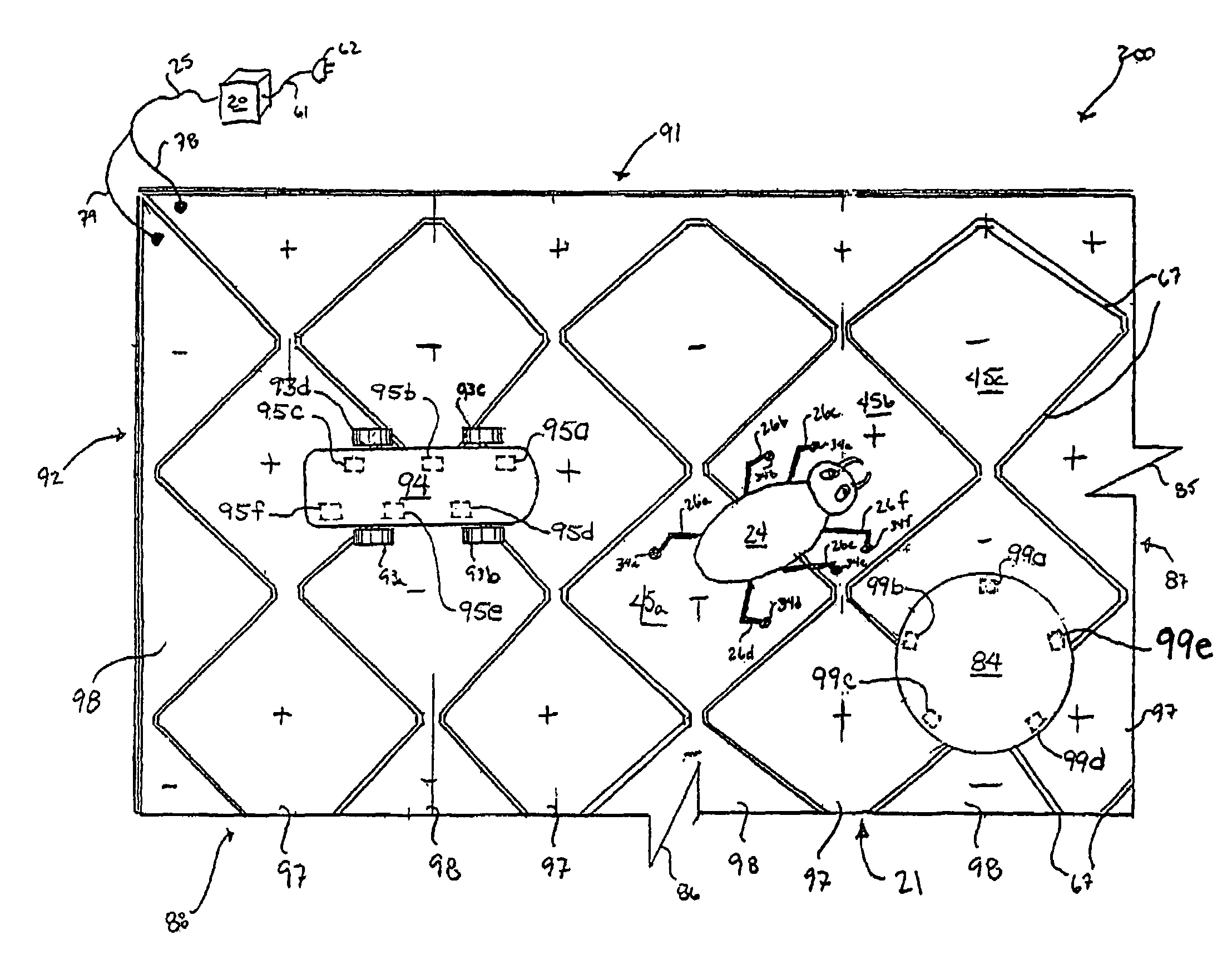
[0029]Three examples of mobile, electrically powered electromechanical devices 24, 84, 94 are shown in FIG. 2a positioned on an electric contact system portion 200, which provides electric power to the electromechanical devices 24, 84, 94 according to this invention. For an overview of the principles of this invention, reference is made first to the electromechanical device 24, which is in the form of an ambulatory mechanical bug such as, but not limited to, those described in co-pending U.S. patent application Ser. No. 10 / 613,915, which is supported by its legs 26 on the surfaces of several of the pad segments 45 of the contact system portion 200. The pad segments 45 are connected via leads 78, 79 to an electric power source 20, and the electromechanical device 24 draws its electric power to operate, e.g., to move around on the contact system portion 200, through its legs 26 from the pad segments 45. As illustrated by the negative (−) and positive (+) symbols on the pad segments 45...


PUM


Abstract

Various contact systems and methods for manufacturing and using such are disclosed herein. Examples of the contact systems include a surface with one set of pads biased at a first voltage level, and another set of pads biased at a second voltage level. Such a contact system can be used, for example, to transfer power to an electromechanical device disposed thereon. In one particular example, the electromechanical device can include a power storage element and two or more couplings. When one of the couplings contacts a pad biased at the first voltage level, and another of the couplings contacts a pad biased at the second voltage level, a circuit is completed where some derivative of the differential between the first voltage level and the second voltage level is placed across the power storage element. Completion of the circuit causes the power storage element to charge. Power can be drawn from the power storage element to operate the electromechanical device.

Description

CROSS REFERENCE TO RELATED CASES[0001]The present application claims the benefit of three U.S. Provisional Patent Applications: U.S. Provisional Patent Application No. 60 / 432,072 entitled “Method and Apparatus for Providing Electrical Power to Devices Arbitrarily Positioned or Moving on a 2-Dimensional Surface”, filed on Dec. 10, 2002, by the inventor of the present application; U.S. Provisional Patent Application No. 60 / 441,794 entitled “Game System Involving a Game Controller and Electromechanical Game Devices”, filed on Jan. 22, 2003, by the inventor of the present application; and U.S. Provisional Patent Application No. 60 / 444,826 entitled “Method and Apparatus to Communicate With and Individually Locate Multiple Remote Devices on a Two-Dimensional Surface”, filed on Feb. 4, 2003, by the inventor of the present application. The entirety of each of the aforementioned provisional patent application Nos. 60 / 432,072, 60 / 441,794, and 60 / 444,826 is incorporated herein by reference for...

Claims


Application Information

Patent Timeline
Patent Type & Authority Patents(United States)
IPC IPC(8): A63F3/00A63F9/24
CPCA63F3/00643A63H18/12A63F2009/2404A63F2009/2407Y10S439/95A63F2009/2442A63F2009/2457A63F2009/247A63F2009/2494A63F2009/2439
Inventor RANDALL, MITCH
Owner FLI CHARGE LLC
Why Eureka
Try Eureka