Voltage-operated layered arrangement

a technology of layered arrangements and voltage, applied in the direction of electroluminescent light sources, thermoelectric devices, electric lighting sources, etc., can solve the problems of failure of the entire electroluminescent layer

Active Publication Date: 2011-07-19
BEIJING XIAOMI MOBILE SOFTWARE CO LTD
View PDF30 Cites 0 Cited by
  • Summary
  • Abstract
  • Description
  • Claims
  • Application Information

AI Technical Summary

Benefits of technology

[0004]It is therefore an object of this invention to make a long life possible for structured layered arrangements.
[0006]By the application of the field-degrading layer in the region of an edge, the local increase in the electrical field at the edge is considerably reduced. The electrical conductivity of the field-degrading layer produces a wider distribution of the field in the region of sharp edges because the field, which previously originated only from the edge, now extends into the functional layer via the adjoining regions of the field-degrading layer as well. Hence, what flows through the functional layer in this area is a current that is only slightly higher than the current in regions where there are no edges, which produces a dramatic reduction in the risk of short circuits in the area in question. Because the conductivity of the field-degrading layer is less than the conductivity of the functional layer, the possibility of a short circuit between the anode and cathode via the field-degrading layer is ruled out.
[0007]In one embodiment of the voltage-operated layered arrangement according to the invention, the functional layer comprises at least one electroluminescent layer. In this case, locally increased field strengths in the region of edges make themselves apparent in the form of degradation of the electroluminescent layer around the edges. The degenerated regions may possibly cease to emit light and may grow and, as the time in operation becomes longer, may result in a short circuit that will cause the entire electroluminescent layer to fail. The presence of the field-degrading layer will prevent any substantial increase in the field in the region of the edges and the regions that emit poorly or not at all will thus not grow nor will they pose any threat to the emitting ability of the electroluminescent layer.
[0008]In a further embodiment, the electroluminescent layer comprises an organic electroluminescent material. In this embodiment, as well as providing the advantages detailed above, the degradation layer constitutes, in addition, a protective layer that is at least an obstacle to the permeation of moisture or oxygen into the organic layer and that has a beneficial effect on the stability of its emitting ability as far as ambient factors are concerned.
[0009]In a further arrangement, the field-degrading layer has an electrical resistance of between 1 Ωcm and 108 Ωcm, and preferably of between 102 Ωcm and 108 Ωcm, and as a particular preference of between 104 Ωcm and 108 Ωcm, and even more preferably of between 106 Ωcm and 108 Ωcm. With a resistance of this range of values, the field-distributing effect of the field-degrading layer is particularly effective and at the same time the possibility of a short circuit between the anode and cathode is ruled out. It is advantageous in this case if the thickness of the field-degrading layer is less than 200 nm.
[0010]In a further arrangement, the field-degrading layer comprises at least one material from the group comprising the inorganic semiconductors, the organic conductive polymers and small conductive organic molecules. These materials are easy to apply as homogeneous layers, and if required as mixed layers, and have uniform electrical properties. The field-distributing effect is thus not subject to local variations in a voltage-operated layered arrangement of large area and can be set repeatably. These materials thus differ, markedly for example, from polymers doped with metallic particles, where variations in the doping concentration could result in widely differing field-degrading properties. The variations in the particle concentration could for example be the result of agglomeration of the particles, particularly if the concentration were to be close to the percolation threshold.

Problems solved by technology

The degenerated regions may possibly cease to emit light and may grow and, as the time in operation becomes longer, may result in a short circuit that will cause the entire electroluminescent layer to fail.

Method used


Image

  • Voltage-operated layered arrangement
  • Voltage-operated layered arrangement

Examples


Embodiment Construction

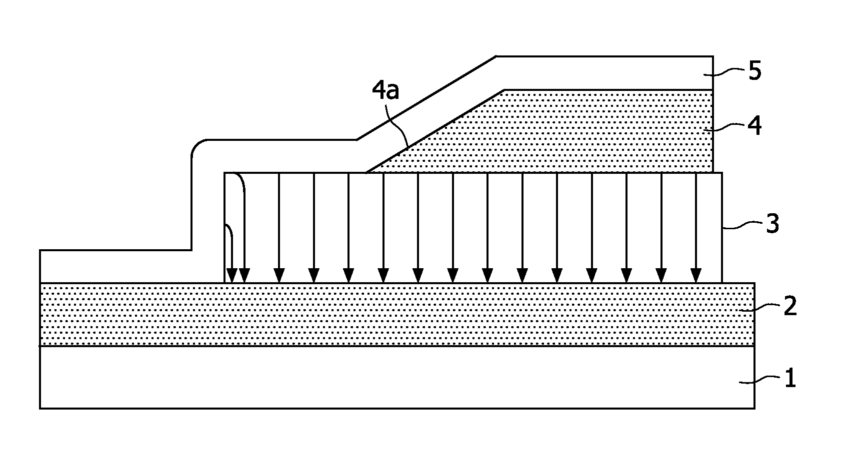
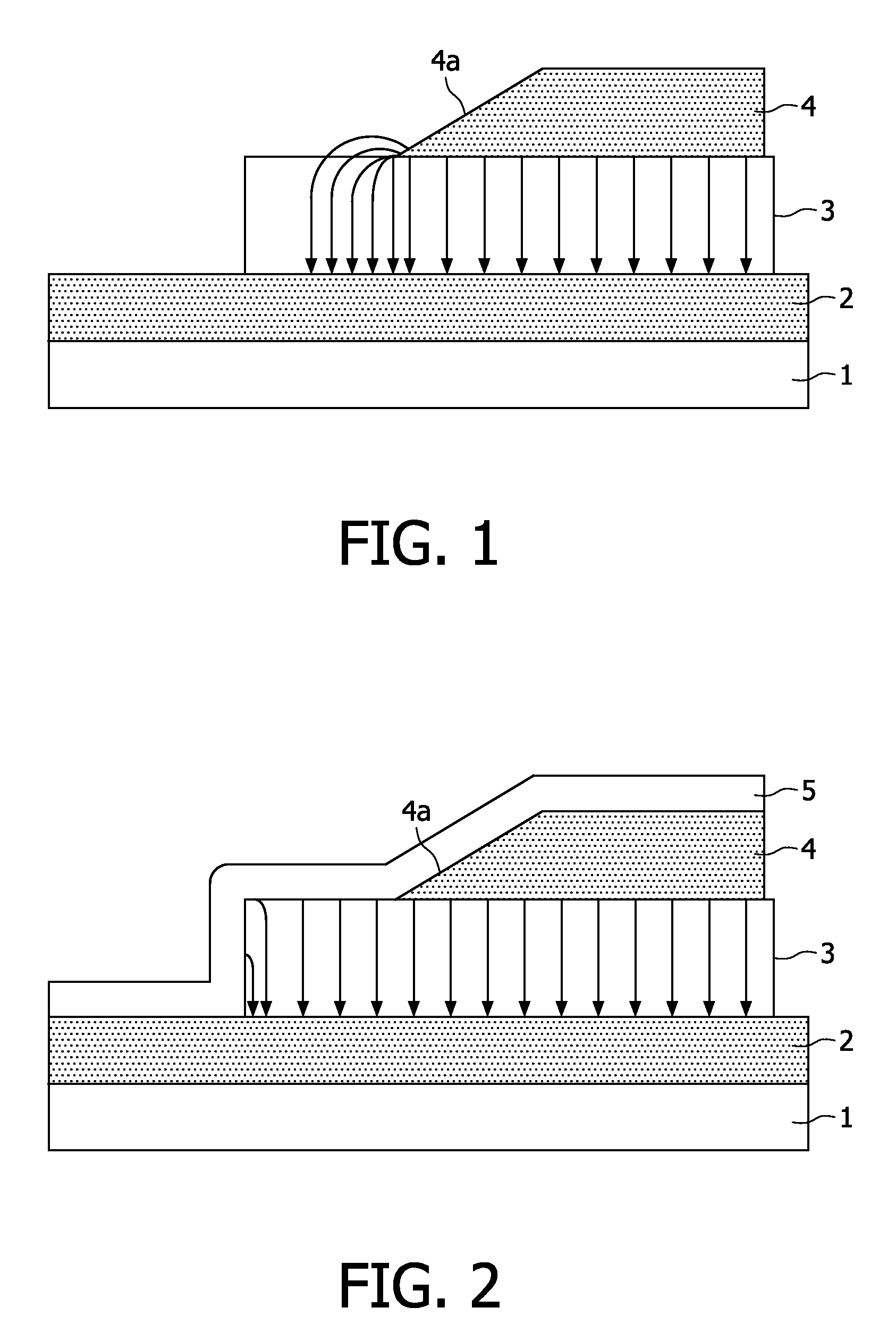
[0021]A voltage-operated layered arrangement of the kind shown in FIG. 1, such for example as an organic electroluminescent arrangement (OLED), comprises individual thin layers the majority of which are produced by dry directional coating processes such for example as vacuum deposition and / or sputtering. What is referred to as a directional coating process is a process in which the material to be applied moves substantially in a straight line from the source to the substrate to be coated. A characteristic of such processes is uncoated regions (shadowed regions) which are situated behind edges, masks, etc. arranged in the region of space between the source and substrate. In such directional coating processes, edges occur as a result of, for example, the structuring of the layered arrangement by masking techniques.

[0022]For an OLED arrangement, a typical operating voltage is of the order of 3 to 10 V between the electrodes 2 and 4. With a typical electrode spacing of 100 nm, that corr...


PUM


Abstract

A voltage-operated layered arrangement comprising a substrate (1), a layered structure (2, 3, 4, 5) that is applied to the substrate and that comprises at least one electrically conductive functional layer (3) arranged between a first electrode (2) and a second electrode (4), and a field-degrading layer (5) that is less electrically conductive than the functional layer (3) and that is applied to the second electrode (4) arranged on the side of the layered structure remote from the substrate in such a way that it covers the second electrode (4) at least in the region of an edge (4a) and connects the second electrode (4) to the first electrode (2) electrically.

Description

[0001]The invention relates to a voltage-operated layered arrangement having a functional layer, and covering layers for the electrical passivation of the layered arrangement, and to a method of producing a layered arrangement of this kind.BACKGROUND OF THE INVENTION[0002]There is a large number of known voltage-operated layered arrangements comprising a plurality of thin layers or thin films including a functional layer for applying an operating voltage, such for example as computer chips, thin-film components or electroluminescent arrangements having inorganic or organic electroluminescent layers. These layered arrangements comprise a layered structure having a functional layer that is arranged between an anode and a cathode for applying an operating voltage across the functional layer. The functional layers are intended for example for the emission of light, as thin-film resistors, as dielectric layers, or for use in other applications. The layered structure is typically applied ...

Claims


Application Information

Patent Timeline
Patent Type & Authority Patents(United States)
IPC IPC(8): H01L21/00
CPCH01L51/5203H01L51/5237H05B33/22H10K50/805H10K50/844
Inventor LOEBL, HANS-PETERBOERNER, HERBERT FRIEDRICH
Owner BEIJING XIAOMI MOBILE SOFTWARE CO LTD
Why Eureka
Try Eureka